Lab 2 - TRANSIT NETWORKING#
1. Objective#
Build Transit Network in Azure, GCP and AWS using Aviatrix Multicloud Transit Hub-and-Spoke Topology.
In this lab, we will use Aviatrix CoPilot to connect three major clouds, i.e. Azure, GCP and AWS. The workloads in VPCs/VNets, in all three clouds, must communicate without manual configuration on the native consoles.
2. Multicloud Connectivity Overview#
Enterprises are relying increasingly on multiple clouds (multicloud) providers. However, setting up the connectivity between those providers is difficult. Moreover, maintaining and monitoring the tunnels is time-consuming and cumbersome to troubleshoot.
Aviatrix simplifies this by providing simple, point-and-click tunnel creation between cloud providers.
Additionally, Aviatrix gives you a single, centralised location from which to troubleshoot and monitor your connections.
3. Topology#
In this lab, as shown in the topology below, we will configure the grey Aviatrix gateways, the grey attachments between Transit-Spoke and the grey peerings between Transit-Transit, but only in the following regions:
AWS: us-east-2
GCP: us-central-1
AZURE: west-us (only spoke1)
The rest of the topology has been preprovisioned to save time, including the test instances/VMs and the Edge inside the on-prem DC.
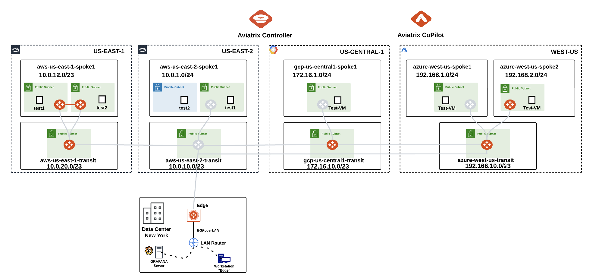
Fig. 28 Initial pre-provisioned topology#
Note
The test VPCs/VNet you created in Lab 1 will not be used in other labs.
For sake of semplicity, in this lab, the Transits will NOT be deployed in pairs. As a best practice, Aviatrix recommends always to deploy two Transits to ensure High Availability.
The CoPilot Dashboard should look something like this:
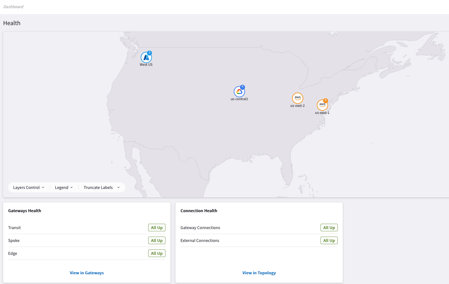
Fig. 29 Dashboard#
Before starting building your multicloud infrastructure, adjust the fetch timers on the CoPilot.
Hint
Go to CoPilot > Settings > Resources > Task Server
Ensure that Fetch Topology, Fetch Instances, Fetch GW Routes and Fetch VPC Routes intervals are set to “1 Second” each and then click on SAVE.
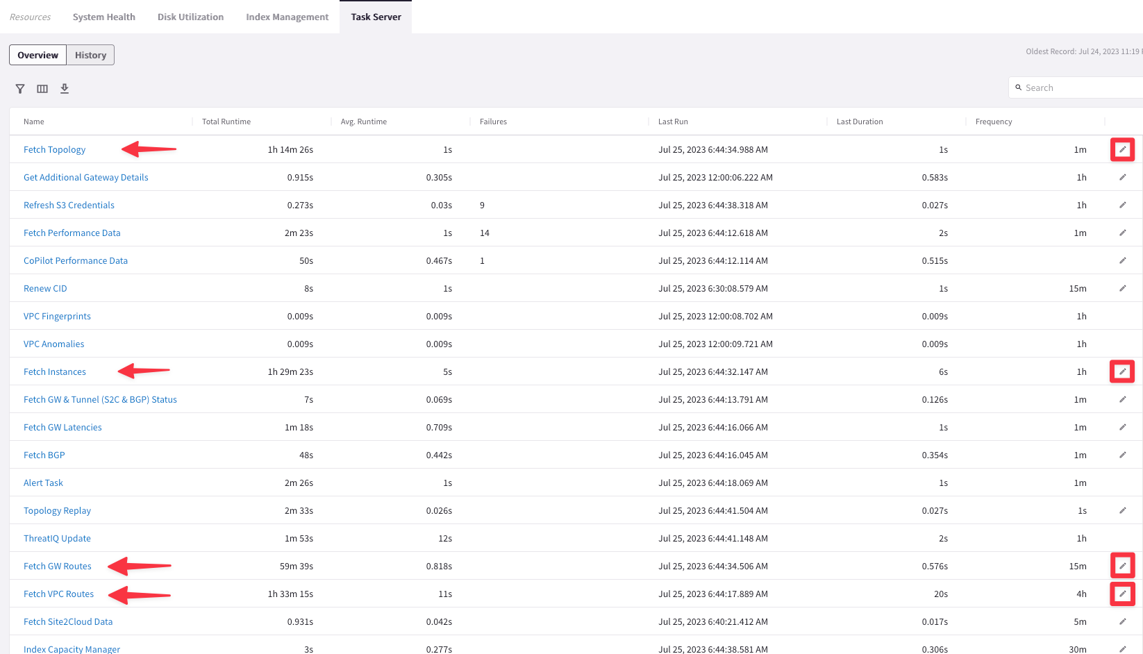
Fig. 30 Task Server#
Caution
The order of the Task Servers on the screenshot above might be different on your CoPilot
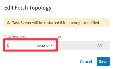
Fig. 31 Fetch Topology#
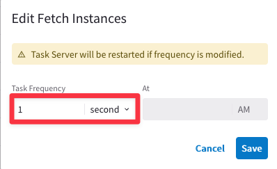
Fig. 32 Fetch Instances#
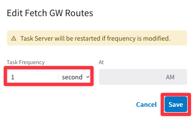
Fig. 33 Fetch GW#
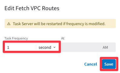
Fig. 34 Fetch VPC#
Afterwards, click on Commit.
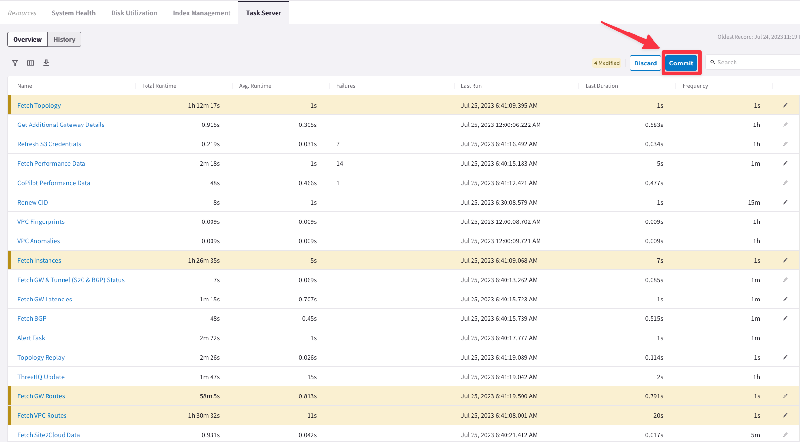
Fig. 35 Commit#
Note
These are very aggressive settings. In a Production environment, you should not set these intervals that frequently!
4. Initial configuration#
Go to CoPilot > Dashboard and check the Gateways Health either of the Spoke GW Clusters or the Transit GW Clusters.
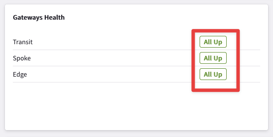
Fig. 36 Transit, Spoke & Edge#
When you begin this lab, you should have six Gateway Clusters (i.e. 3x Transit GWs clusters, 2x Spoke GWs clusters and 1x Edge cluster) in your pod.
3x Transit GW Clusters
2x Spoke GW Clusters
1x Edge GW Cluster
If you go to CoPilot > Cloud Fabric > Gateways > Overview (default tab), you will notice that the number of Transit Gateways is set to three indeed, whereas the number of Spoke Gateways is set to two.
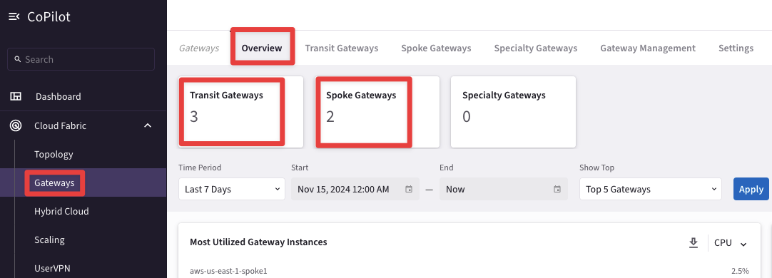
Fig. 37 These are Clusters of GWs#
This view within the Cloud Fabric section does not indicate the exact number of gateways but it refers to the number of clusters, per each type of gateway.
Go to CoPilot > Cloud Fabric > Gateways > Transit Gateways and expand the three drop-down lists.
You can find out that there are a total of Three Transit Gateways (Public IPs may differ):

Fig. 38 Transit GWs Clusters#
Note
You can deploy up to maximum two Transit Gateways per each Transit VPC/VNet/VCN.
Go to CoPilot > Cloud Fabric > Gateways > Spoke Gateways and expand the unique drop-down list. You can find out that there are a total of three Spoke Gateways (once again, the Public IPs may differ):

Fig. 39 Spoke GWs Clusters#
You can notice that the cluster in AWS comprises two Spoke Gateways, whereas in Azure there is just a single Spoke Gateway. This is a valid deployment. The number of Spoke Gateways that you should deploy per each Spoke VPC/VNet/VCN is dictated by your architecture design.
Note
You can deploy up to maximum fifteen Spoke Gateways per each Spoke VPC/VNet/VCN.
4.1. Aviatrix Transit Gateways#
In this section, you will experience the power and simplicity of the Aviatrix platform by deploying (i.e. creating) 4 gateways:
Transit gateway in AWS US East 2: aws-us-east-2-transit
Spoke gateway in AWS US East 2: aws-us-east-2-spoke1
Spoke gateway in Azure West US: azure-west-us-spoke1
Spoke gateway in GCP US Central 1: gcp-us-central1-spoke1
Warning
Please pay close attention to each step, as a misconfiguration could result in 20+ minutes of lost time!
Go to CoPilot > Cloud Fabric > Gateways > Transit Gateways > + Transit Gateway

Fig. 40 +Transit Gateway#
Deploy Aviatrix Transit Gateways in AWS East-2 region. To save time, Aviatrix Transit Gateways in Azure, GCP and AWS east-1 region have already been pre-deployed in pairs for this lab.
4.1.1.Transit Gateway in AWS US-EAST-2#
Ensure these parameters are entered in the pop-up window "Create Transit Gateway".
Name: aws-us-east-2-transit
Cloud: AWS (Standard)
Account: aws-account
Region: us-east-2 (Ohio)
VPC ID: aws-us-east-2-transit (Make sure you don’t select aws-us-east-2-spoke1 VPC)
Instance Size: c6in.large
High Performance Encryption: On
Attach to Subnet: us-east-2a
Public IP: Allocate New Static Public IP
Note
As soon as you select High Performance Encryption, /26 subnets will appear in the drop-down window.
Click SAVE.
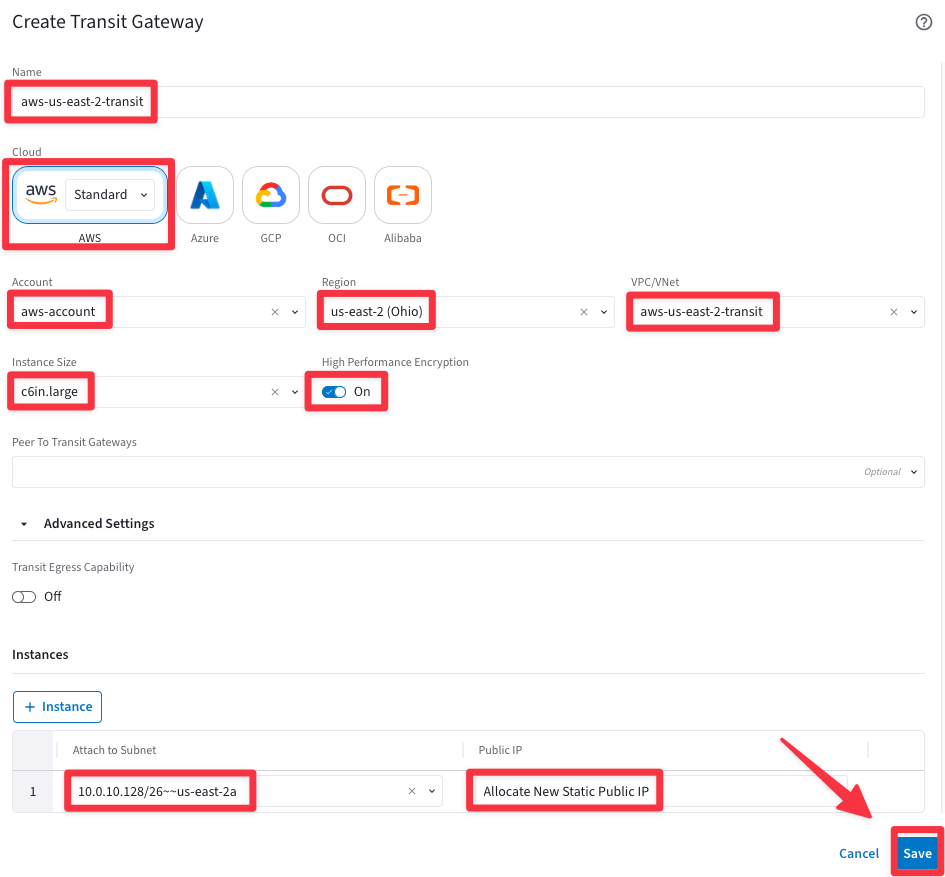
Fig. 41 Create Transit Gateway#
Note
Only one Transit Gateway will be deployed in VPC aws-us-east2-transit.
You will immediately get a message as follows.

Fig. 42 Gateway deployment in progress#
You may check the status of the gateway creation in the top right corner by expanding the task icon.
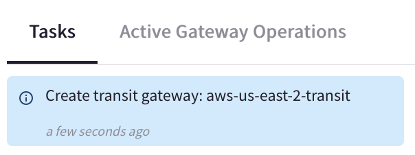
Fig. 43 Task icon#
This action will instantiate the Transit Gateway with the following name:
aws-us-east-2-transit
Meanwhile the deployment is happening, you may proceed to the next section of this lab guide to deploy your Spoke gateways.
4.2. Aviatrix Spoke Gateways#
Navigate to the tab immediately to the right, which is Spoke Gateways.
This is CoPilot > Cloud Fabric > Gateways > Spoke Gateways > + Spoke Gateway.

Fig. 44 +Spoke Gateway#
4.2.1. Spoke Gateway in AWS#
Ensure these parameters are entered in the pop-up window "Create Spoke Gateway".
Note
Only one Spoke Gateway will be deployed in VPC aws-us-east2-spoke1.
Name: aws-us-east-2-spoke1
Cloud: AWS (Standard)
Account: aws-account
Region: us-east-2 (Ohio)
VPC ID: aws-us-east-2-spoke1 (Make sure you don’t select aws-us-east-2-transit VPC)
Instance Size: t2.medium
High Performance Encryption: Off
Attach to Subnet: aws-us-east-2-spoke1-Public-1-us-east-2a
Public IP: Allocate New Static Public IP
Click SAVE.
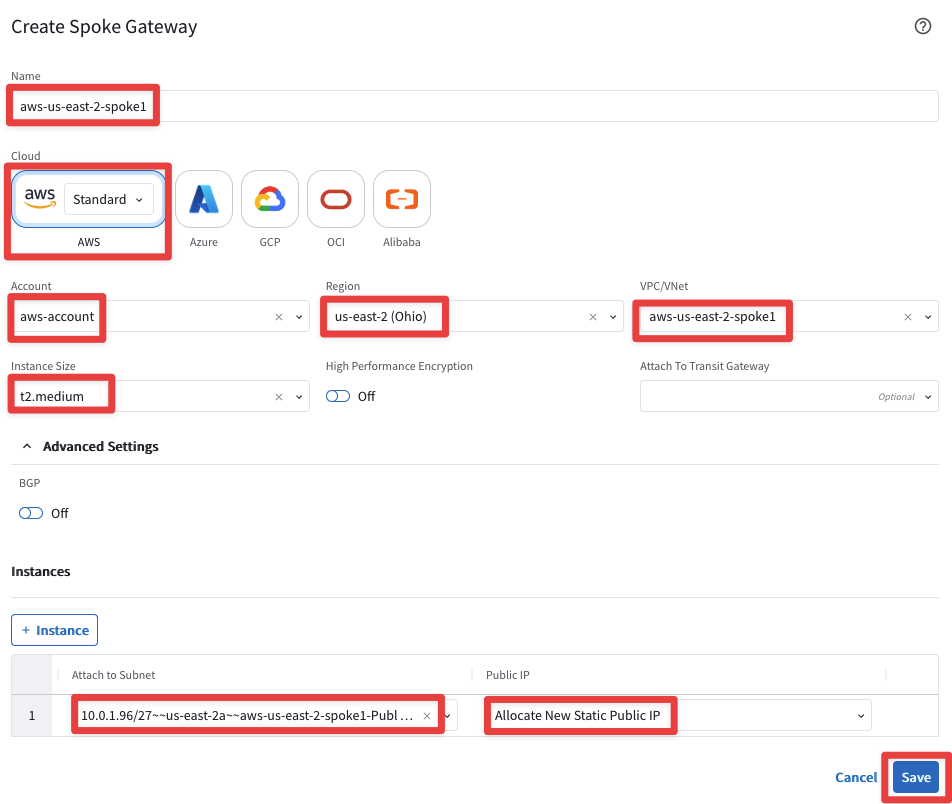
Fig. 45 Create Spoke Gateway in AWS#
While the gateway is being created, you may proceed to the next section.
4.2.2. Spoke Gateway in Azure#
Repeat the previous steps for Azure, click on the button "+ Spoke Gateway" and ensure these parameters are entered in the pop-up window "Create Spoke Gateway".
Note
Only one Spoke Gateway will be deployed in VNet azure-west-us-spoke1.
Name: azure-west-us-spoke1
Cloud: Azure (Global)
Account: azure-account
Region: West US
VNet: azure-west-us-spoke1 (Make sure you don’t select azure-west-us-spoke2 VPC)
Instance Size: Standard_B2ms
High Performance Encryption: Off
Attach to Subnet: azure-west-us-spoke1-Public-gateway-subnet-1
Public IP: Allocate New Static Public IP
Warning
Make sure you do not select the subnets that begins with az-1, az-2, or az-3. It is Aviatrix’s recommended practice to deploy gateways in subnets with ‘gateway’ in their name, whereas workloads in subnets that do not have ‘gateway’ in their name).
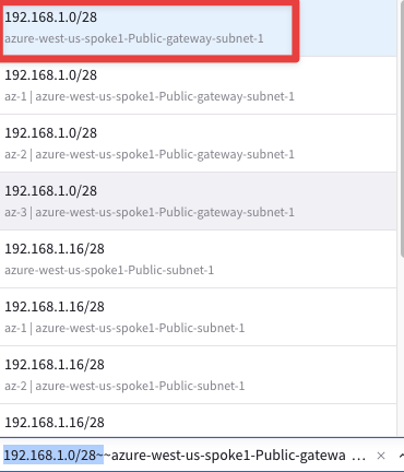
Fig. 46 Subnet selection#
Do not forget to click on SAVE.
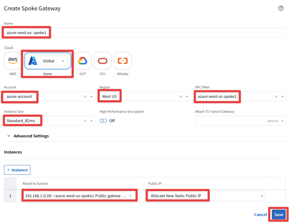
Fig. 47 Spoke GW in Azure#
While the gateway is being created, you may proceed to the next section.
4.2.3. Spoke Gateway in GCP#
Repeat the previous steps for GCP. Ensure these parameters are entered in the pop-up window "Create Spoke Gateway".
Warning
Only one Spoke Gateway will be deployed in VPC gcp-us-central1-spoke1.
Name: gcp-us-central1-spoke1
Cloud: GCP
Account: gcp-account
VPC: gcp-us-central1-spoke1 (Make sure you don’t select gcp-us-west2-spoke1 VPC)
Instance Size: n1-standard-1
High Performance Encryption: Off
Attach to Subnet: gcp-us-central1-spoke1-sub1
Zone: us-central1-a
Public IP: Allocate New Static Public IP
Click SAVE.
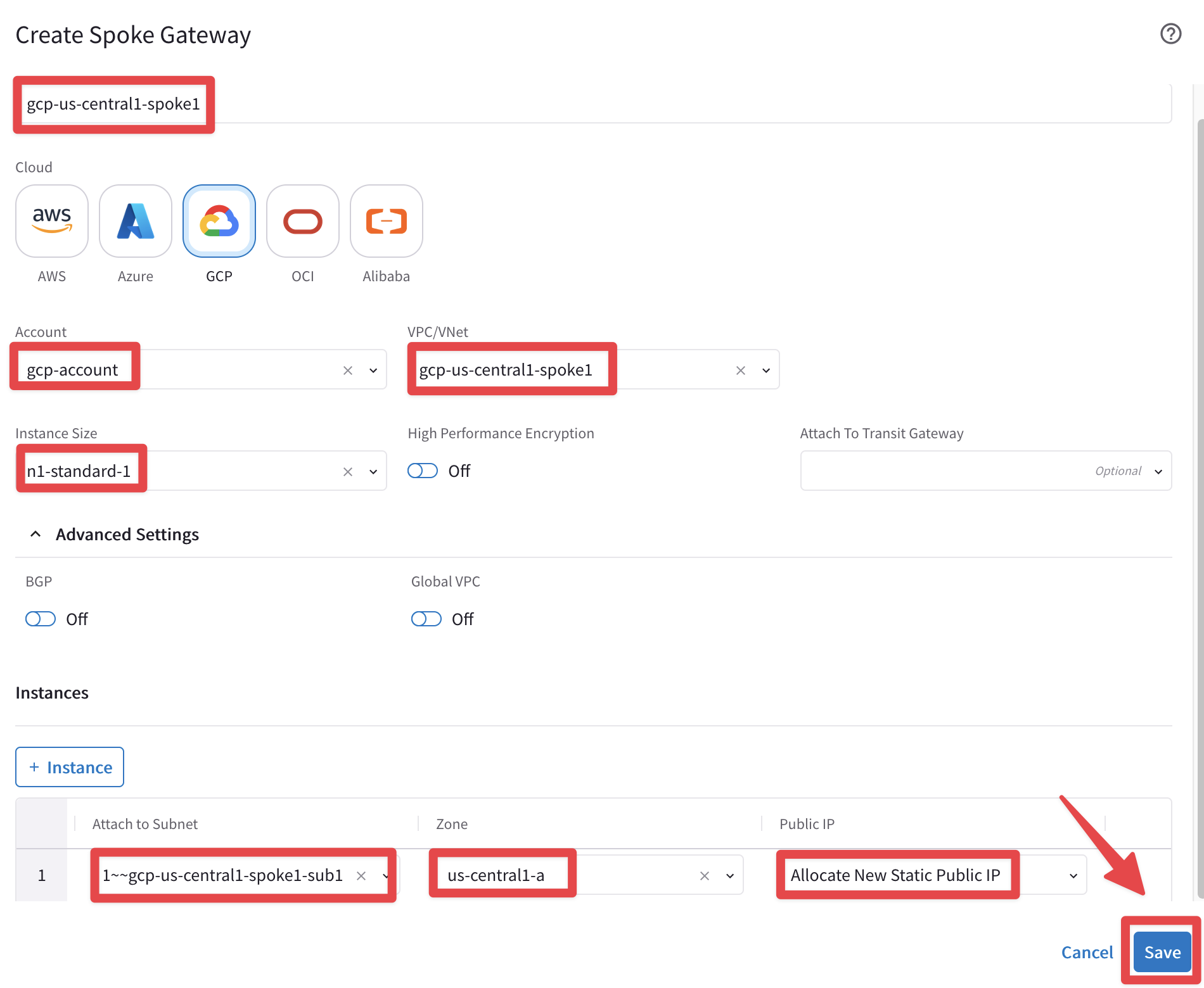
Fig. 48 Spoke GW in GCP#
Caution
You can see the progress of gateway deployment at any time by expanding the task icon in the top right corner of the CoPilot.
Bear in mind that the gateways’ creation process can take several minutes to complete, therefore please be patient!
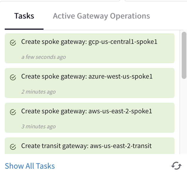
Fig. 49 Deployment in progress#
Once all gateways have been created, confirm from CoPilot > Cloud Fabric > Gateways > Overview (default TAB) the presence of a total of nine GWs Clusters!

Fig. 50 Dashboard#
After created the Transit gateway in AWS US-EAST-1 region and the single Spoke gateways in each cloud, this is how the topology would look like.
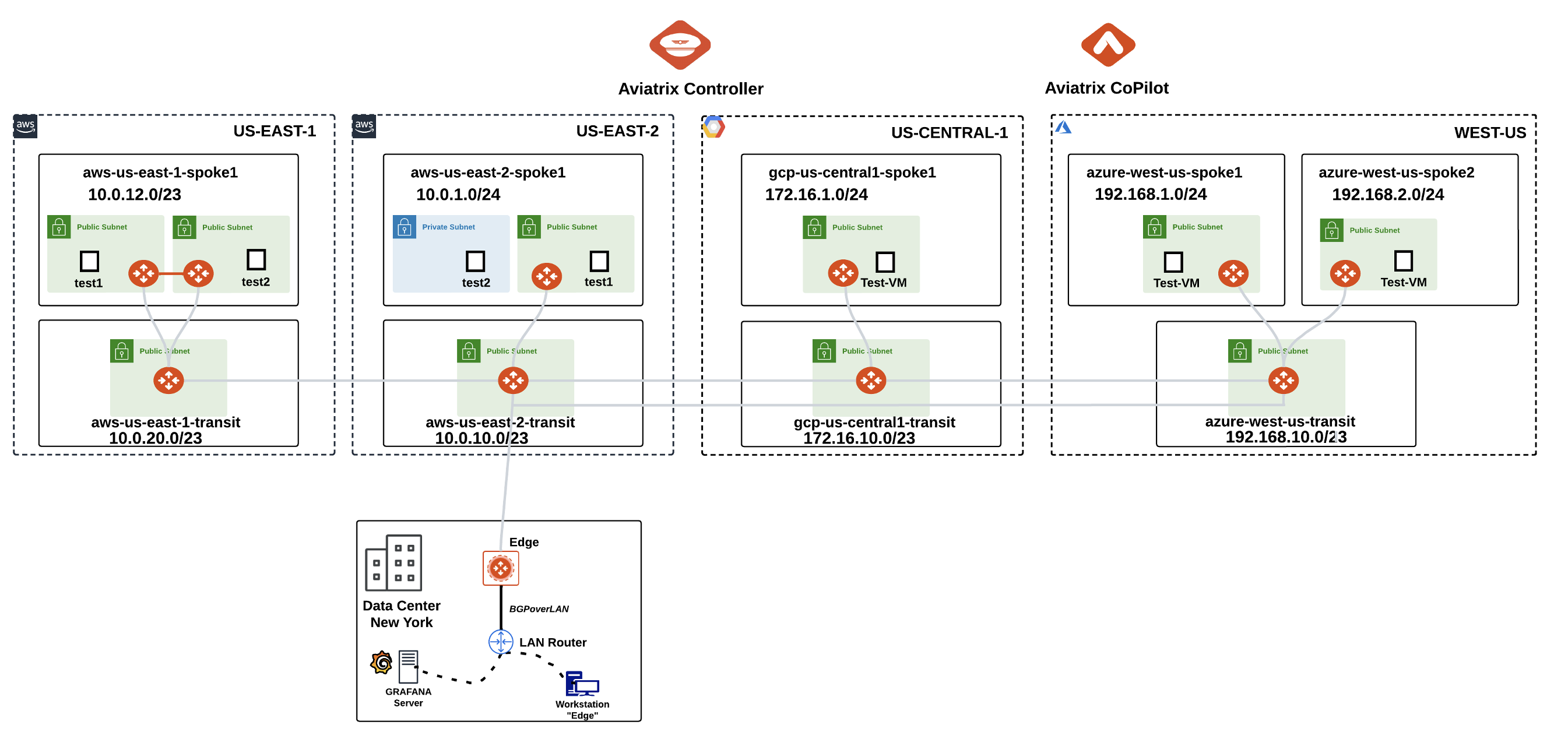
Fig. 51 Overview of the new topology#
4.3. Explore the Cloud Fabric#
Go to CoPilot > Cloud Fabric > Topology > Overview (default tab), then click on the "Managed" button to only showing the Managed VPCs!
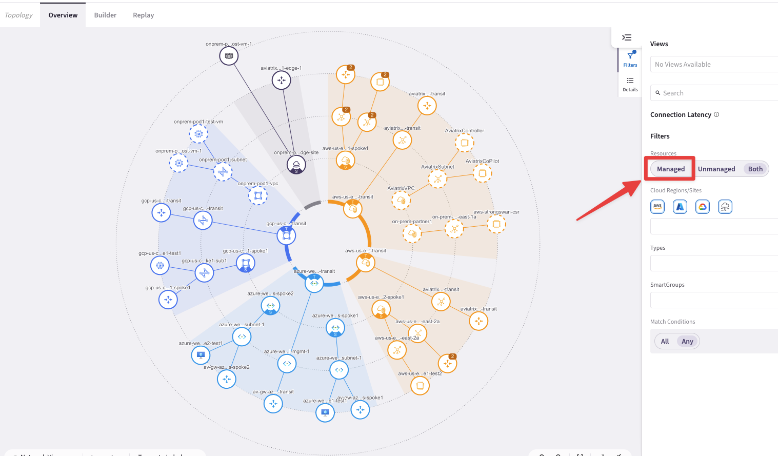
Fig. 52 Managed VPCs and Unmanaged VPCs#
Note
Managed VPC = Indicates an Aviatrix gateway is running in the VPC/VNet.
Unmanaged VPC = Indicates no Aviatrix gateways exist in the VPC/VNet.
Now you can click on the "Collapse all VPC/VNets" button on the bottom right-hand side, as depicted below.
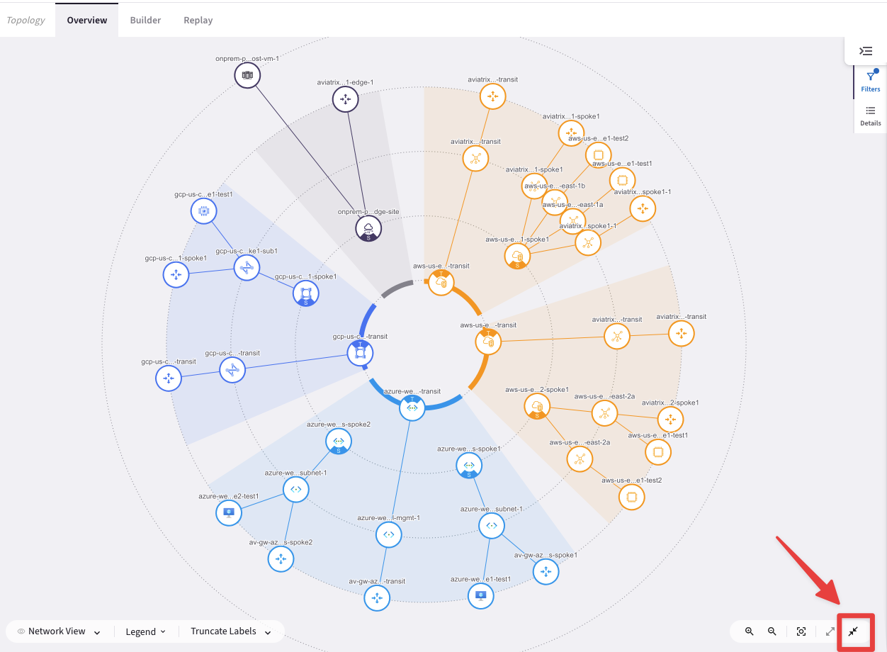
Fig. 53 Collapse button#
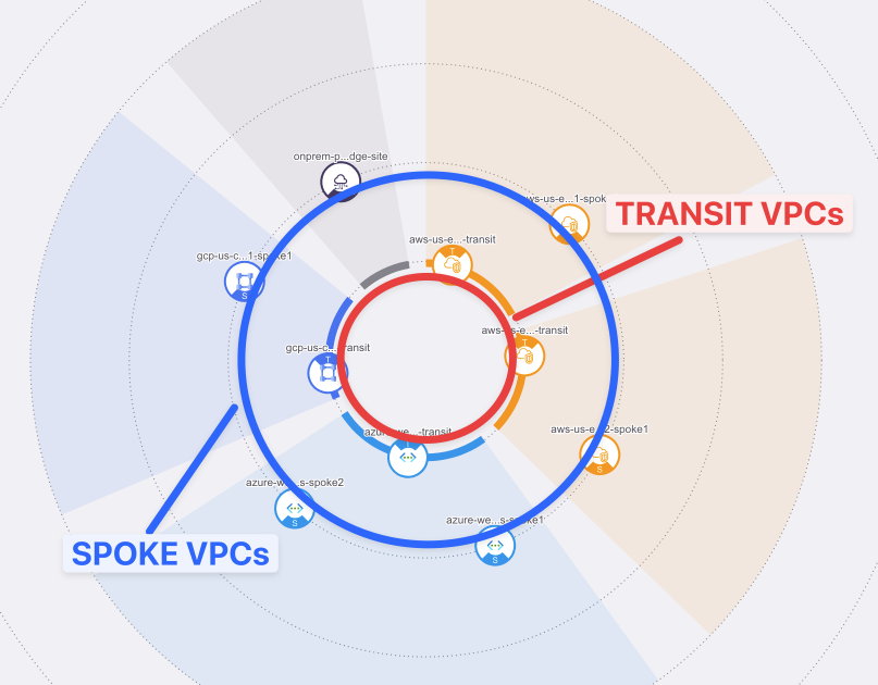
Fig. 54 VPC circles#
Important
The inner circle represents the Transit Gateway VPCs, whereas the outer one represents the Spoke Gateway VPCs.
It is clearly shown at this stage that the spokes are not connected to the transits yet.
In addition, you can explore the components of any of the gateways in terms of subnets and Virtual Machines that reside within the VPC/VNet.
4.4 Aviatrix Spoke to Transit Gateways Attachments#
In this section you are going to attach the Aviatrix Spoke Gateways created above in each cloud, to their corresponding Aviatrix Transit Gateways.
4.4.1. Spoke to Transit Attachment in AWS#
Go to CoPilot > Cloud Fabric > Gateways > Spoke Gateways and edit the Spoke Gateway aws-us-east-2-spoke1, clicking on the pencil icon:

Fig. 55 Attachment for AWS#
Select the Transit Gateway aws-us-east-2-transit (do not select the aws-us-east-1-transit) from the drop-down window "Attach To Transit Gateway", and then click on Save.
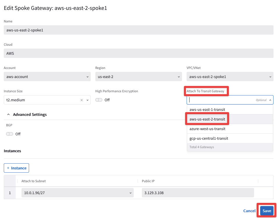
Fig. 56 Edit Spoke in AWS#
You will see immediately a message informing that the updating is in progress.

Fig. 57 Update in progress#
4.4.2 Spoke to Transit Attachment in Azure#
azure-west-us-spoke1 to azure-west-us-transit
Edit the Spoke Gateway azure-west-us-spoke1 (not the spoke2), clicking on the pencil icon.

Fig. 58 Edit spoke in Azure#
Select the Transit Gateway azure-west-us-transit from the drop-down window "Attach To Transit Gateway", and then click on Save.
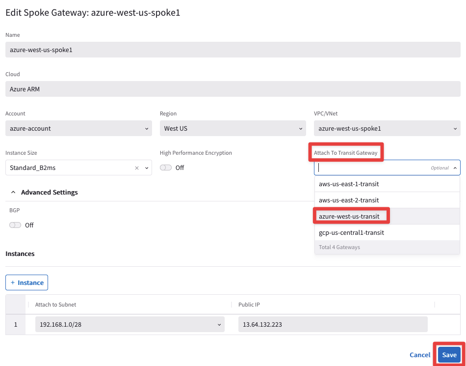
Fig. 59 Attachment in Azure#
4.4.3. Spoke to Transit Attachment in GCP#
gcp-us-central1-spoke1 to gcp-us-central1-transit
Edit the Spoke Gateway gcp-us-central-spoke1, clicking on the pencil icon:

Fig. 60 Edit spoke in GCP#
Select the Transit Gateway gcp-us-central1-transit from the drop-down window "Attach To Transit Gateway", and then click on Save.
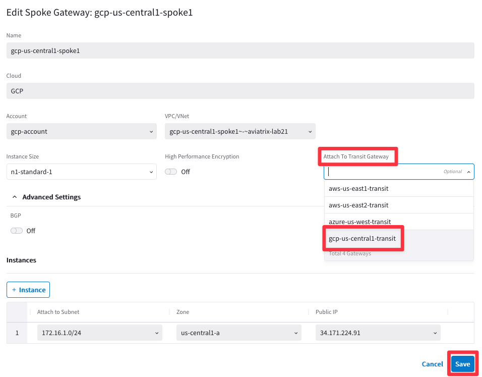
Fig. 61 Attachment in GCP#
Look for these three confirmations through the task icon, before proceeding.
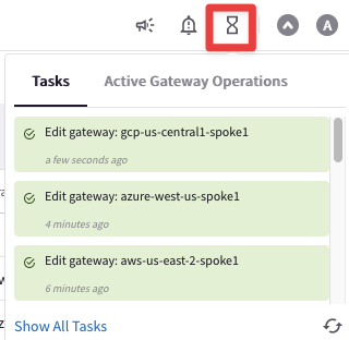
Fig. 62 Confirmations#
At this point, after attaching Spoke Gateways to their respective Transit Gateways, this is what the overall topology would look like.
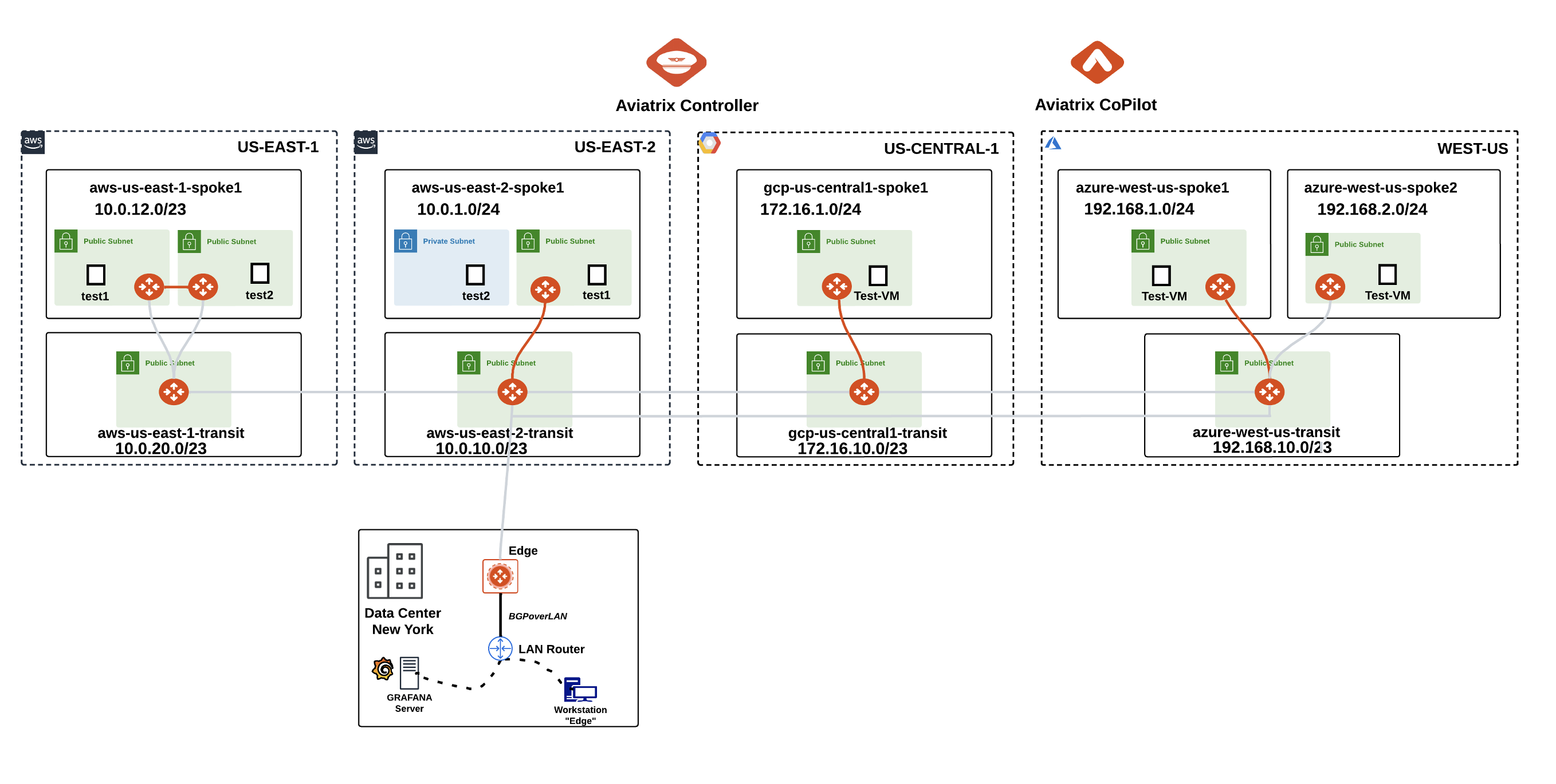
Fig. 63 New state of the Dynamic Topology#
Note
The Spoke Gateway azure-west-us-spoke2 will be attached to its Transit Gateway in a subsequent lab, likewise the Spoke Gateways in AWS us-east-1 will be attached to the Transit Gateway in the same region only in a subsequent lab.
4.5. CoPilot Verification of Spoke-Transit Attachments#
Go to CoPilot > Cloud Fabric > Topology > Overview
Now, verify the spoke-transit attachments. You can see the dotted lines connecting the 3 spoke gateways to their respective transits.
Tip
Be patient, it will take some minutes before seeing the changes reflected into the topology. Refresh the web page to see the change reflected on the map!
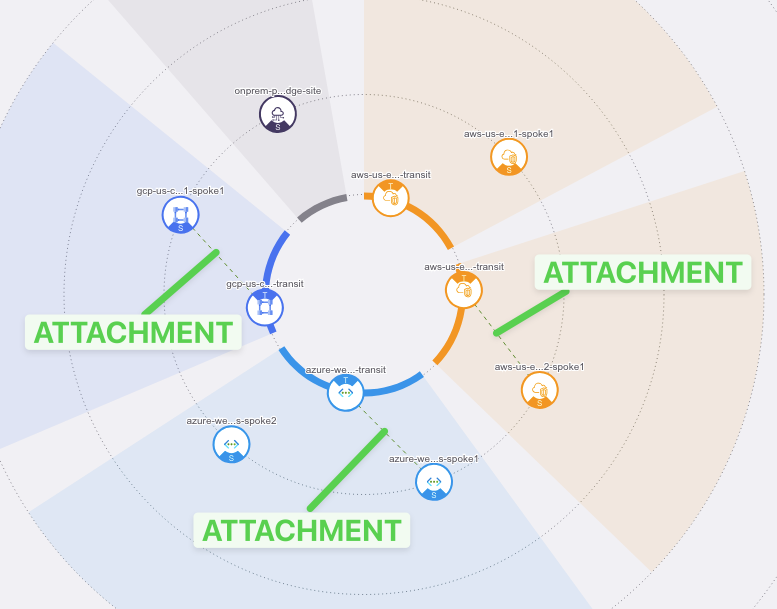
Fig. 64 Attachments#
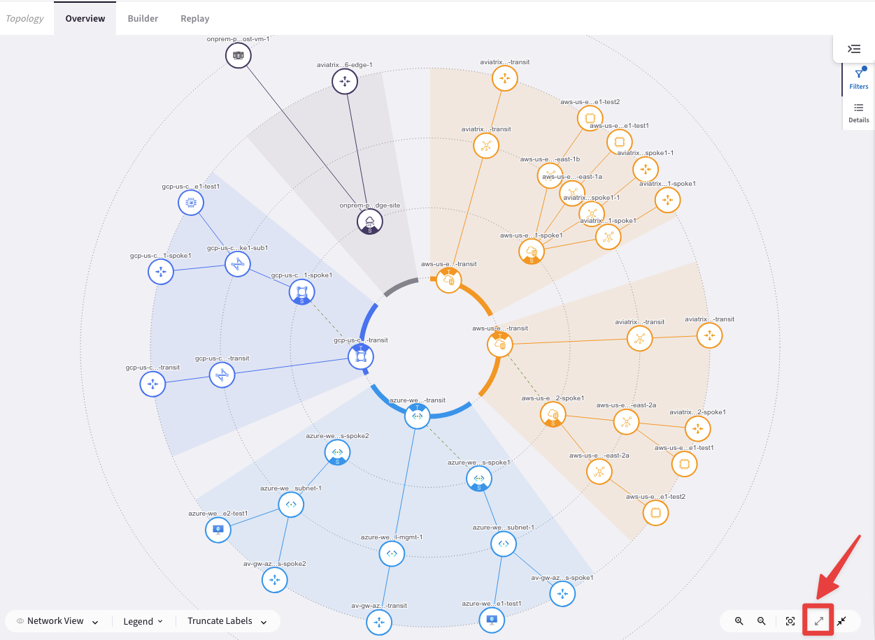
Fig. 65 Expanded Topology#
Click on the "Legend" button to figure out what those icons represent.
Important
Dashed line = Default IPSec tunnel
Solid line = HPE IPSec tunnel
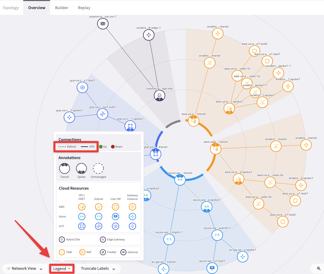
Fig. 66 Legend#
4.6. Multicloud Transit Peerings#
In this section you are going to establish the peerings among the Aviatrix Transit Gateways.
Warning
Transit peering is bidirectional.
You do not need to configure peering in the opposite direction.
Go back to CoPilot > Cloud Fabric > Gateways > Transit Gateways
4.6.1. AWS and Azure#
aws-us-east-2-transit to azure-west-us-transit
Edit the Transit Gateway aws-us-east-2-transit, clicking on the pencil icon:

Fig. 67 Edit Transit in AWS#
Select the Transit Gateway azure-west-us-transit from the drop-down window "Peer To Transit Gateways", and then click on Save.
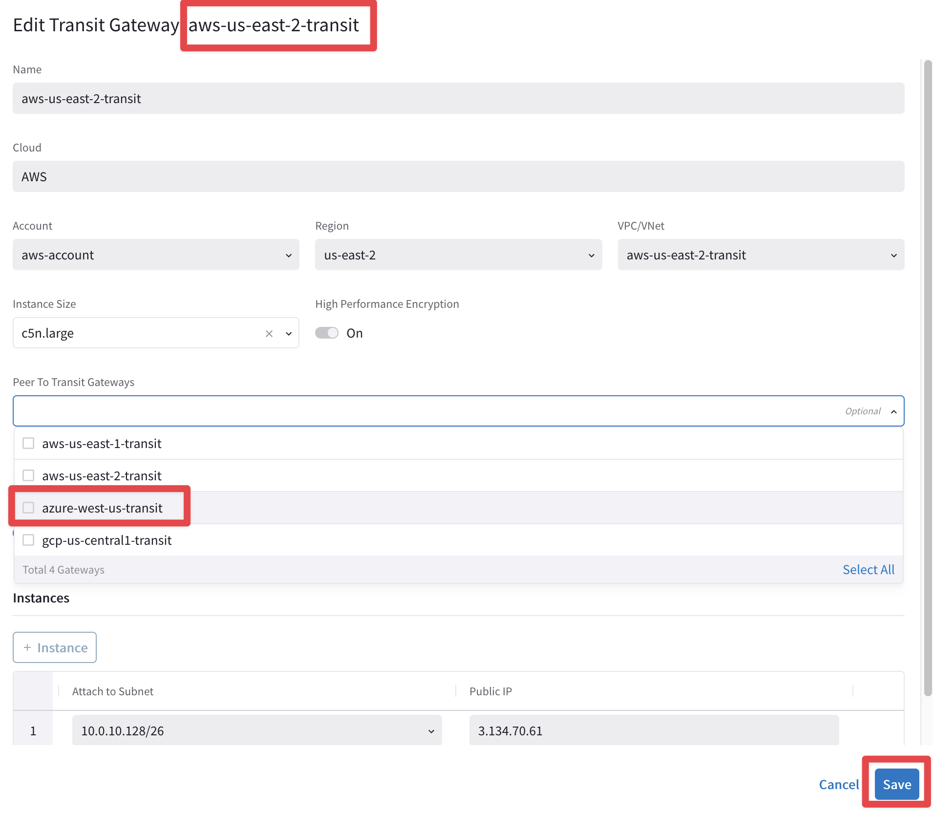
Fig. 68 Peering AWS-Azure#
4.6.2 Azure and GCP#
azure-west-us-transit to gcp-us-central1-transit
Edit the Transit Gateway azure-west-us-transit, clicking on the pencil icon:

Fig. 69 Edit Transit in Azure#
Select the Transit Gateway gcp-us-central1-transit from the drop-down window "Peer To Transit Gateways", and then click on Save.
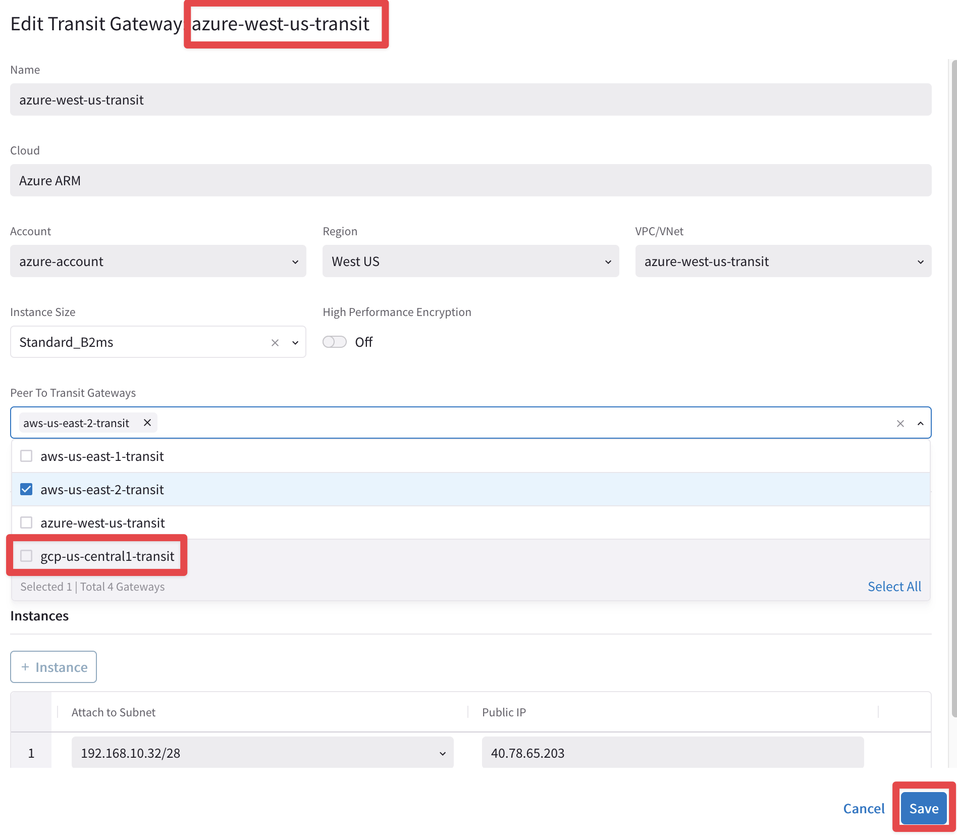
Fig. 70 Peering Azure-GCP#
4.6.3. GCP and AWS#
gcp-us-central1-transit to aws-us-east-2-transit
Edit the Transit Gateway gcp-us-central1-transit, clicking on the pencil icon:

Fig. 71 Edit Transit in GCP#
Select the Transit Gateway aws-us-east-2-transit (not the east-1 !) from the drop-down window "Peer To Transit Gateways", and then click on Save.
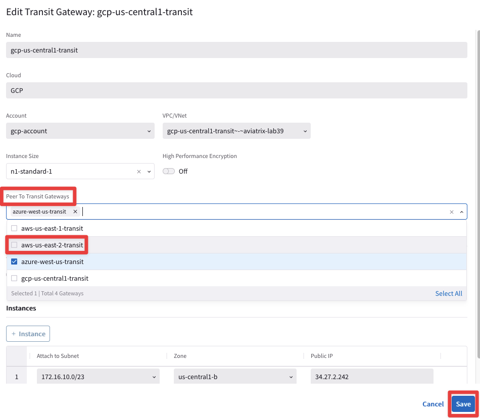
Fig. 72 Peering GCP-AWS#
At this point, this is what the overall topology would look like:
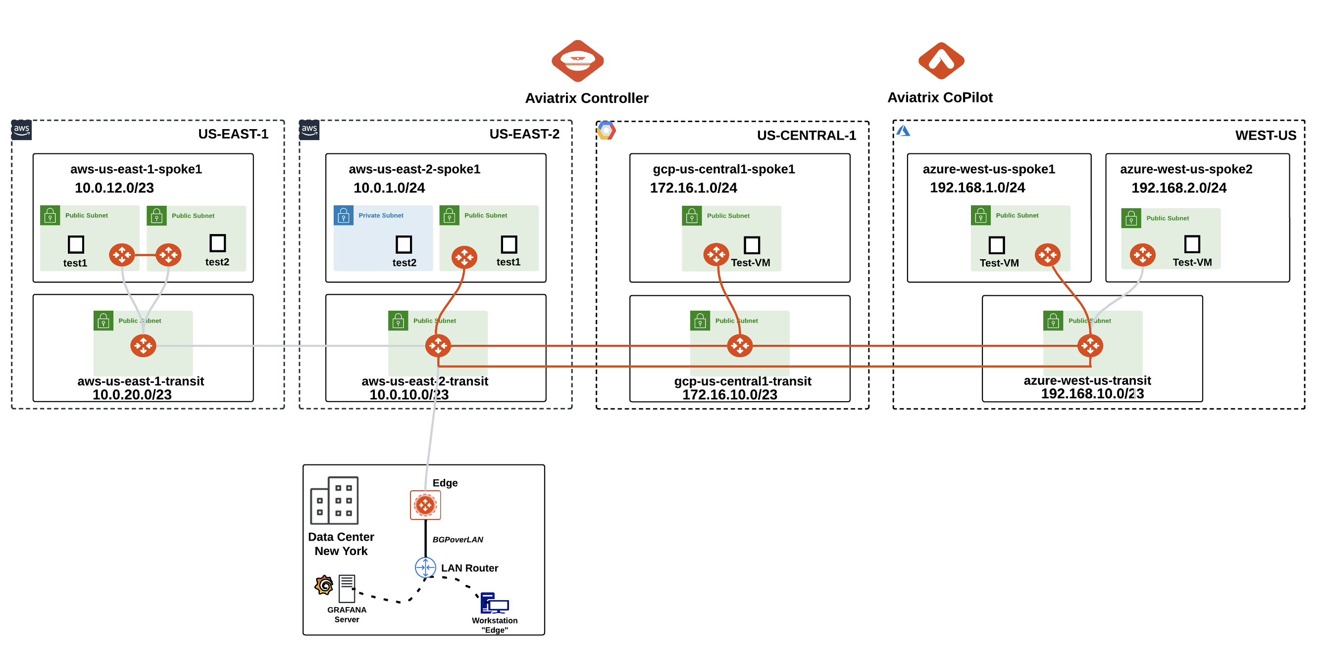
Fig. 73 New Topopology state after Peerings deployment#
Note
Please pay close attention that the following pending elements will be completed only in a subsequent lab:
Attachment between aws-us-east-1-spoke1 and aws-us-east-1-transit
Peering between aws-us-east-1-transit and aws-us-east-2-transit
Attachment between azure-west-us-spoke2 and azure-west-us-transit
Attachment between aws-us-east-2-transit and on-prem-dc-edge
5. Verification#
5.1. Verification of Transit Peerings on CoPilot(Cloud Fabric)#
Go to CoPilot > Cloud Fabric > Gateways > Transit Gateways, select the Transit Gateway aws-us-east-2-transit, then select the Attachments" tab and finally select the "Transit-Transit Peering" tab: you will see one connection per each peering, that correspond to the two IPSec tunnels.
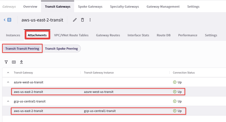
Fig. 74 Verification#
5.2. Verification of Transit Peerings on CoPilot (Topology)#
Go to CoPilot > Cloud Fabric > Topology > Overview
Note
Refresh the web page!
Verify transit-transit peering. You can now see the dotted lines in the inner circle representing the configured full mesh peering between the three transits.
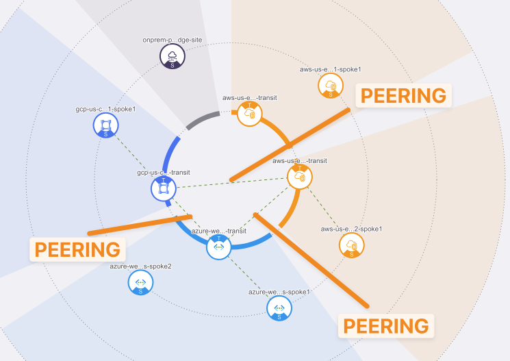
Fig. 75 Peerings#
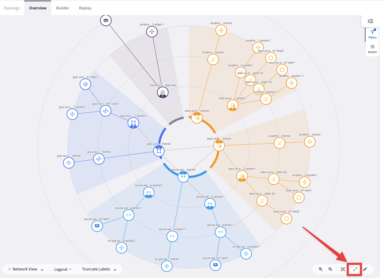
Fig. 76 Expanded Topology#
5.3. Route Info DB#
Route Info DB is akin to the Routing Information Base (RIB). It will provide the overall routing information of a Transit Gateway known by the CoPilot.
Go to CoPilot > Cloud Fabric > Gateways > Transit Gateways and select the Transit Gateway aws-us-east-2-transit:
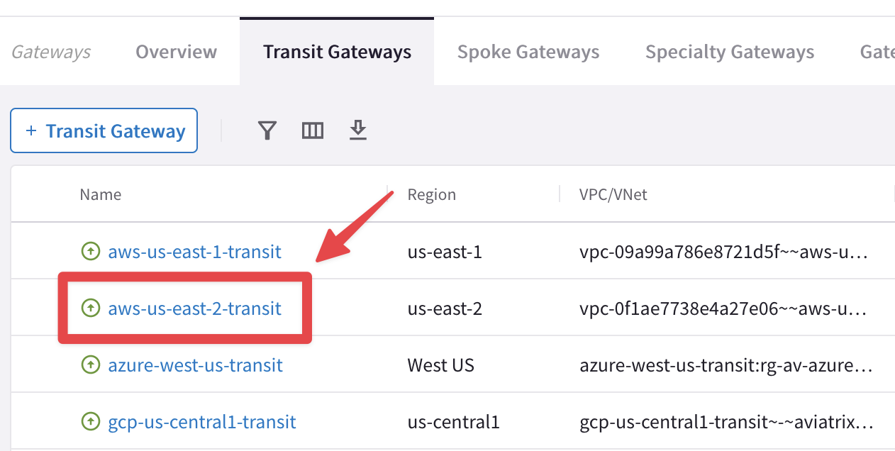
Fig. 77 Explore Transit in AWS#
Then select the "Route DB" tab.
Pay special attention to “Best Routes”, its prefixes, type and metric value:
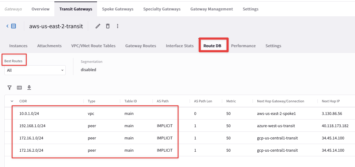
Fig. 78 Route DB#
5.4. Connectivity#
Verify each test instance can ping each other.
Open three terminal windows to SSH to the public IPs of the 3 spoke test instances/VMs in each cloud.
Then ping the private IPs of each other VMs to test the Multi-Cloud connectivity.
Refer to your pod portal for the public/private IPs or retrieve them from the topology.
Important
Refresh the web page, to see the changes reflected into your CoPilot’s topology!
Note
POD PORTAL:
Both public DNS names and private IP addresses of the test instances are retrievable from your personal portal.

Fig. 79 POD Portal info#
Note
TOPOLOGY (CoPilot > Cloud Fabric > Topology):
Explore the aws-us-east-2-spoke1 VPC and select the instance aws-us-east-2-spoke1-test1 with the EC2 instance logo, then check its properties: you will be able to fetch both Public and Private IP addresses.
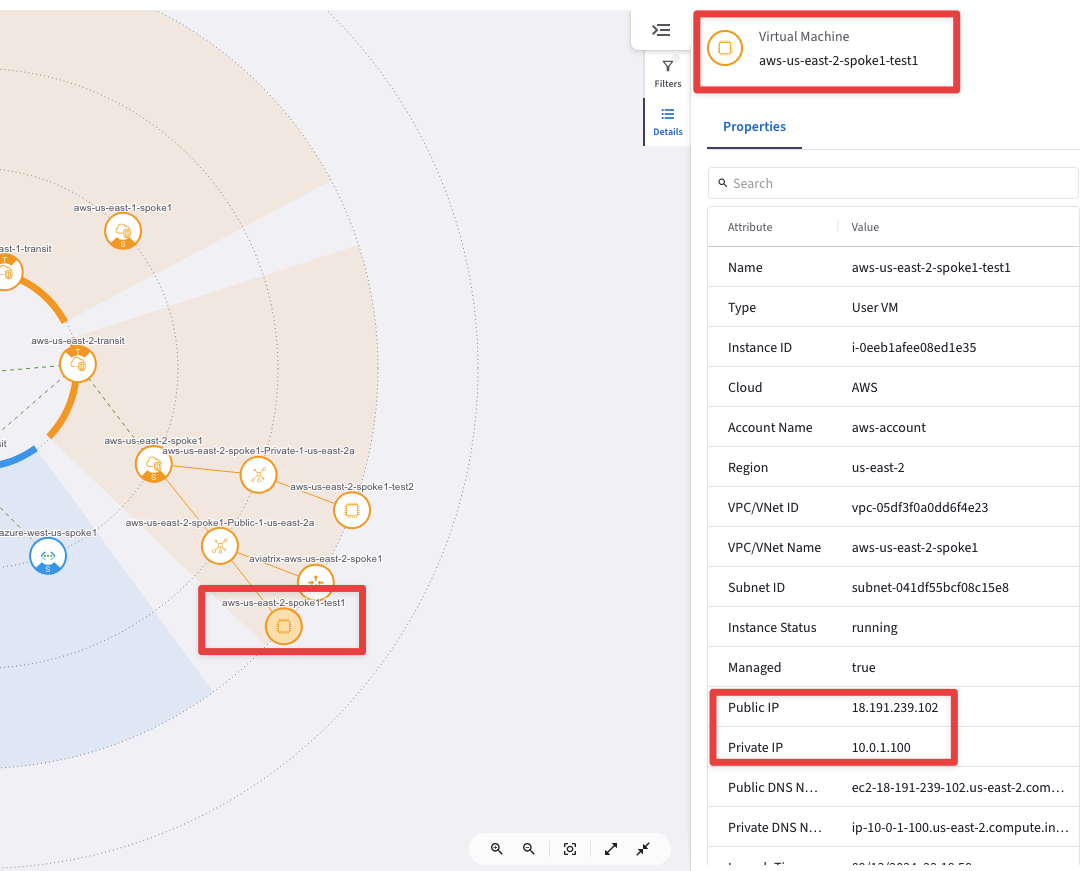
Fig. 80 Test Instance Properties#
Note
Do not select the instance with the Aviatrix logo!
You can’t SSH to any Aviatrix GWs !
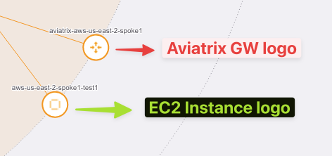
Fig. 81 Different Logos#
SSH into aws-us-east-2-spoke1-test1 (ssh student@public_ip)
SSH into azure-west-us-spoke1-test1 (ssh student@public_ip)
SSH into gcp-us-central1-spoke1-test1 (ssh student@public_ip)
Run ping from the AWS instance to verify connectivity to Azure and GCP:
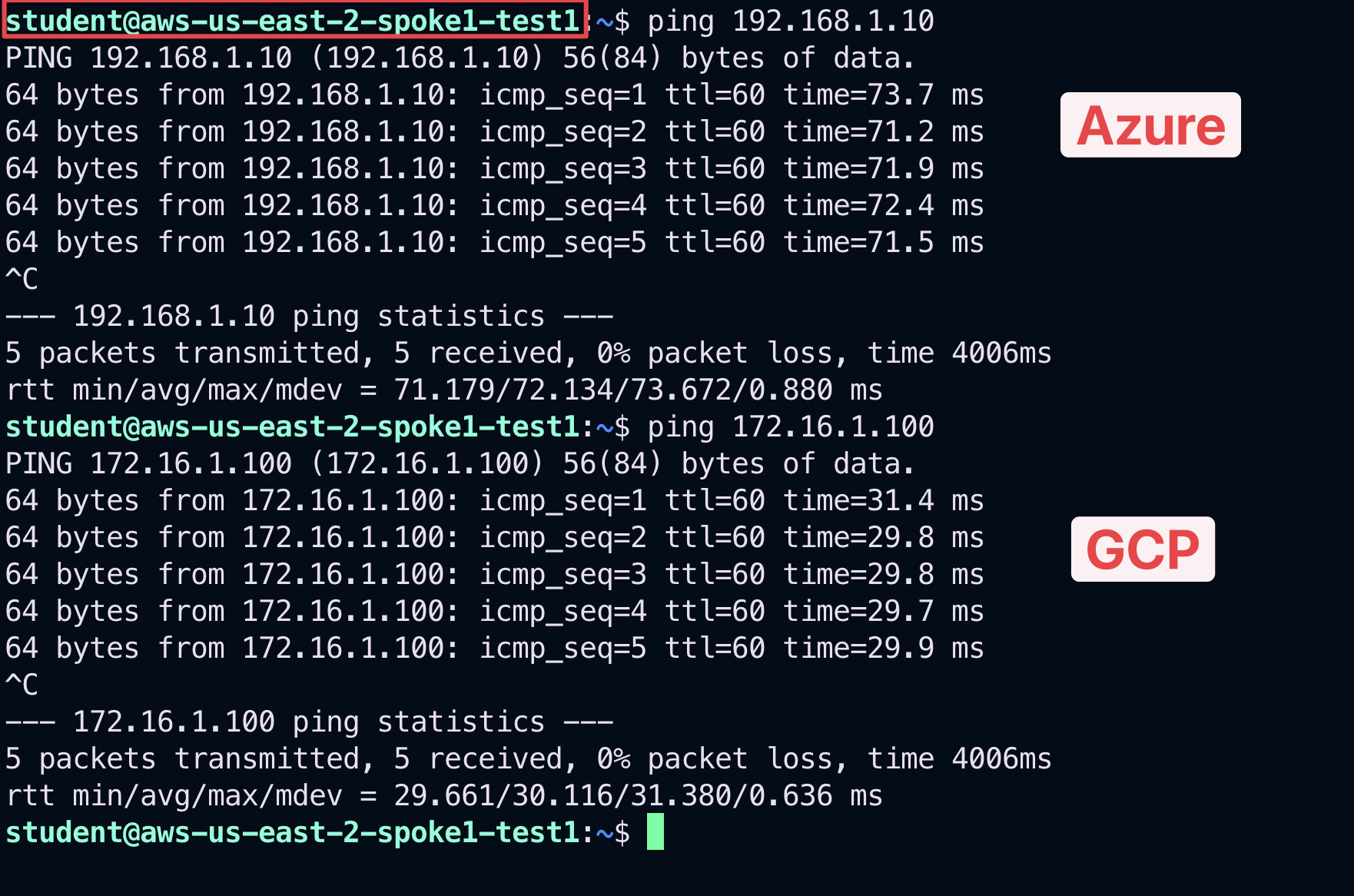
Fig. 82 Ping from AWS#
Run ping from Azure VM to verify connectivity to AWS and GCP:
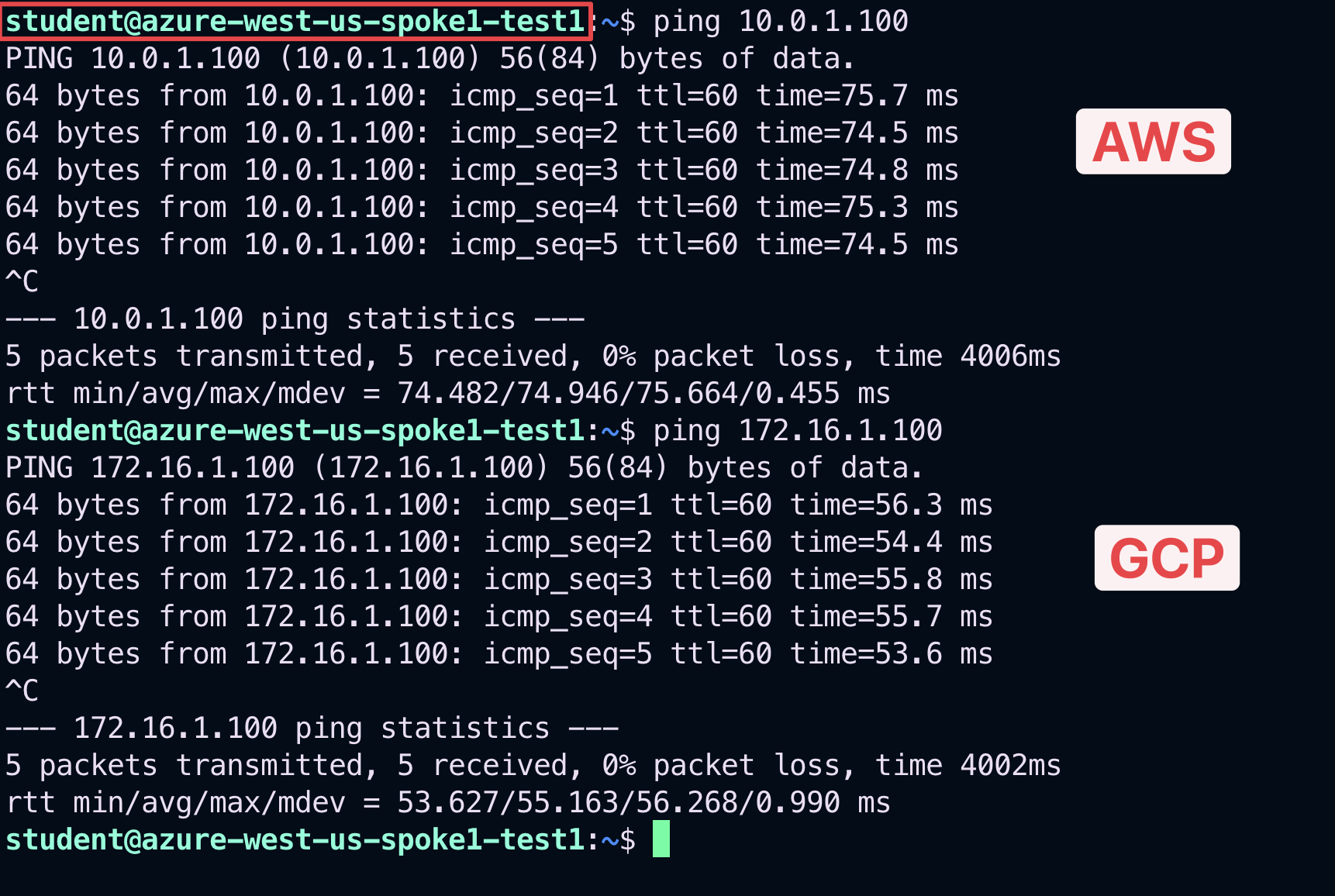
Fig. 83 Ping from Azure#
Run ping from GCP VM to verify connectivity to Azure and AWS:
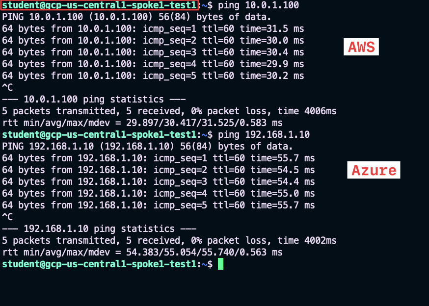
Fig. 84 Ping from GCP#
