Lab 3 - NETWORK SEGMENTATION#
1. Objective#
Implement network segmentation between workloads across multicloud and on-premises environments using network domains.
Note
Network Segmentation will be extended to on-premises in the Site2Cloud lab.
2. Network Segmentation Overview#
Enterprises can define their network domains (aka segments) and group VNets/VPCs/VCNs with similar security policies without requiring firewall solutions.
Aviatrix transits and spokes architecture (aka Hub & Spoke architecture) help enterprises create customised segments and onboard branches, partners and customers in their respective segments so no partner can communicate with each other unless desired.
3. Topology#
In this lab, we will use Aviatrix CoPilot to enable Network Segmentation in Azure, AWS and GCP, in order to segregate VPC/VNet with similarities. At this point, there is a flat routing domain and the communication among the three CSPs occurs through the Transit Core Backbone layer.
You will create two segments: Green and Blue.
Green VPC resources in AWS and Azure can communicate with each other, while access is restricted to Blue VPC resources in GCP. Later, we will ease this restriction with a Connection Policy: Blue and Green segments will be able to communicate with others as well.
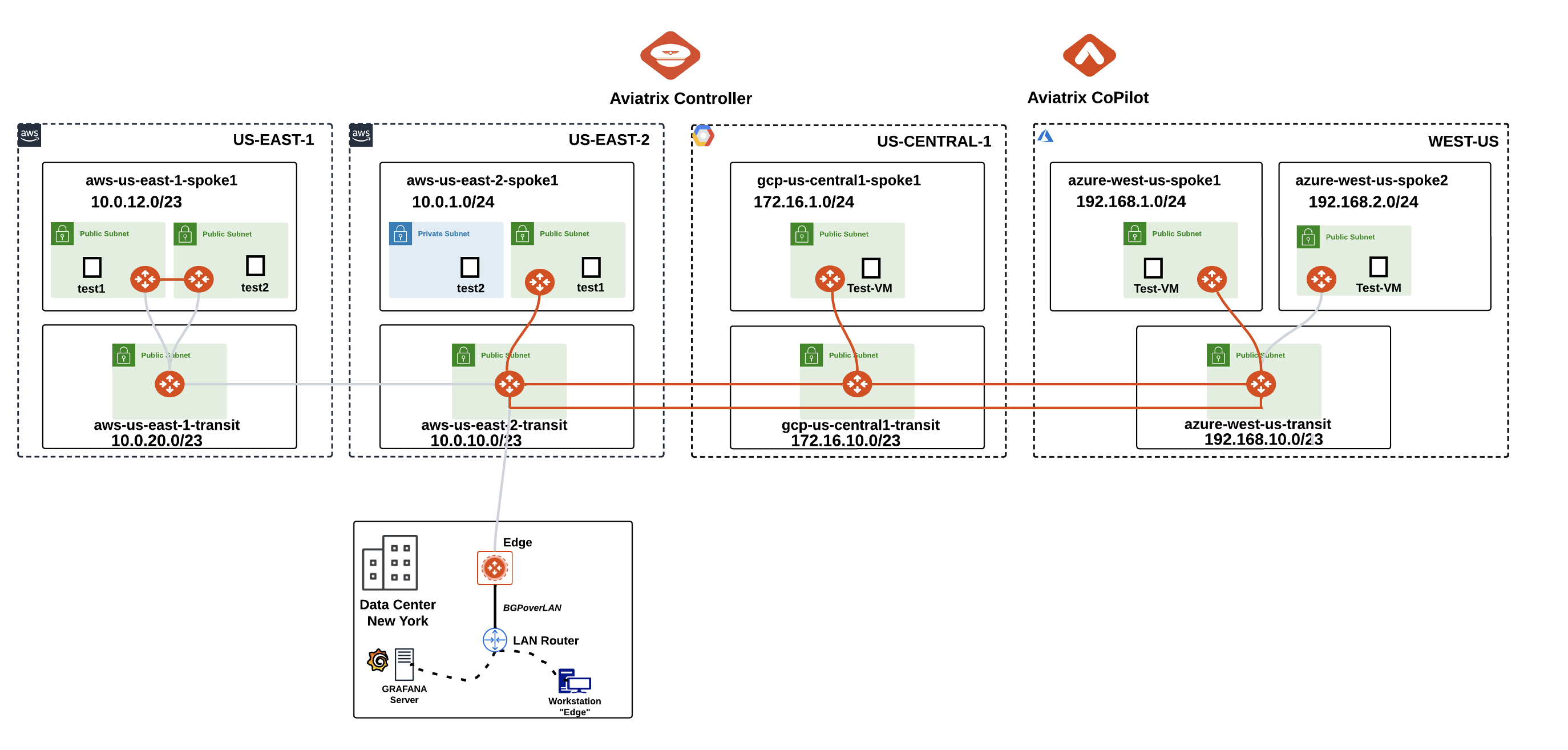
Fig. 85 Topology for Lab 3#
4. Configuration#
4.1. Aviatrix Transit Gateways#
Go to CoPilot > Networking > Network Segmentation > Network Domains > Transit Gateways:
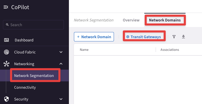
Fig. 86 Enable the feature#
Enable all three Aviatrix Transit Gateways in Azure, GCP and AWS (us-east-2 only for now) for network segmentation as shown below:
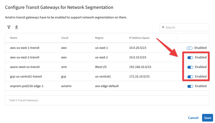
Fig. 87 Enable Segmentation on the relevant Transit GWs#
4.2 Network Domains#
Go to CoPilot > Networking > Network Segmentation > Network Domains > + Network Domain
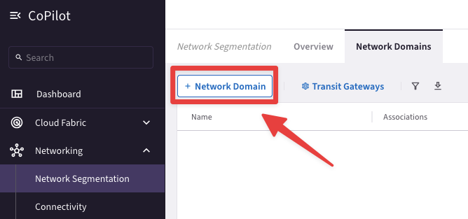
Fig. 88 Network Domain Creation#
Create two network domains (Green and Blue) and associate them to their respective Spokes as follows:
Green- azure-west-us-spoke1 (do not select azure-west-us-spoke2)
Green - aws-us-east-2-spoke1 (do not select aws-us-east-1-spoke1)
Blue - gcp-us-central1-spoke1
Click on Save after creating each Network Domain.
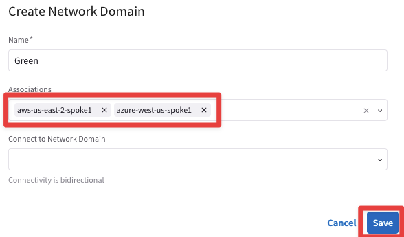
Fig. 89 Green network domain#
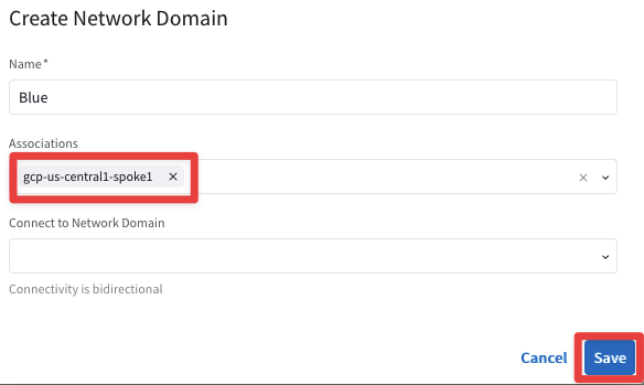
Fig. 90 Blue network domain#
This is what the lab topology looks like after enabling network segmentation:
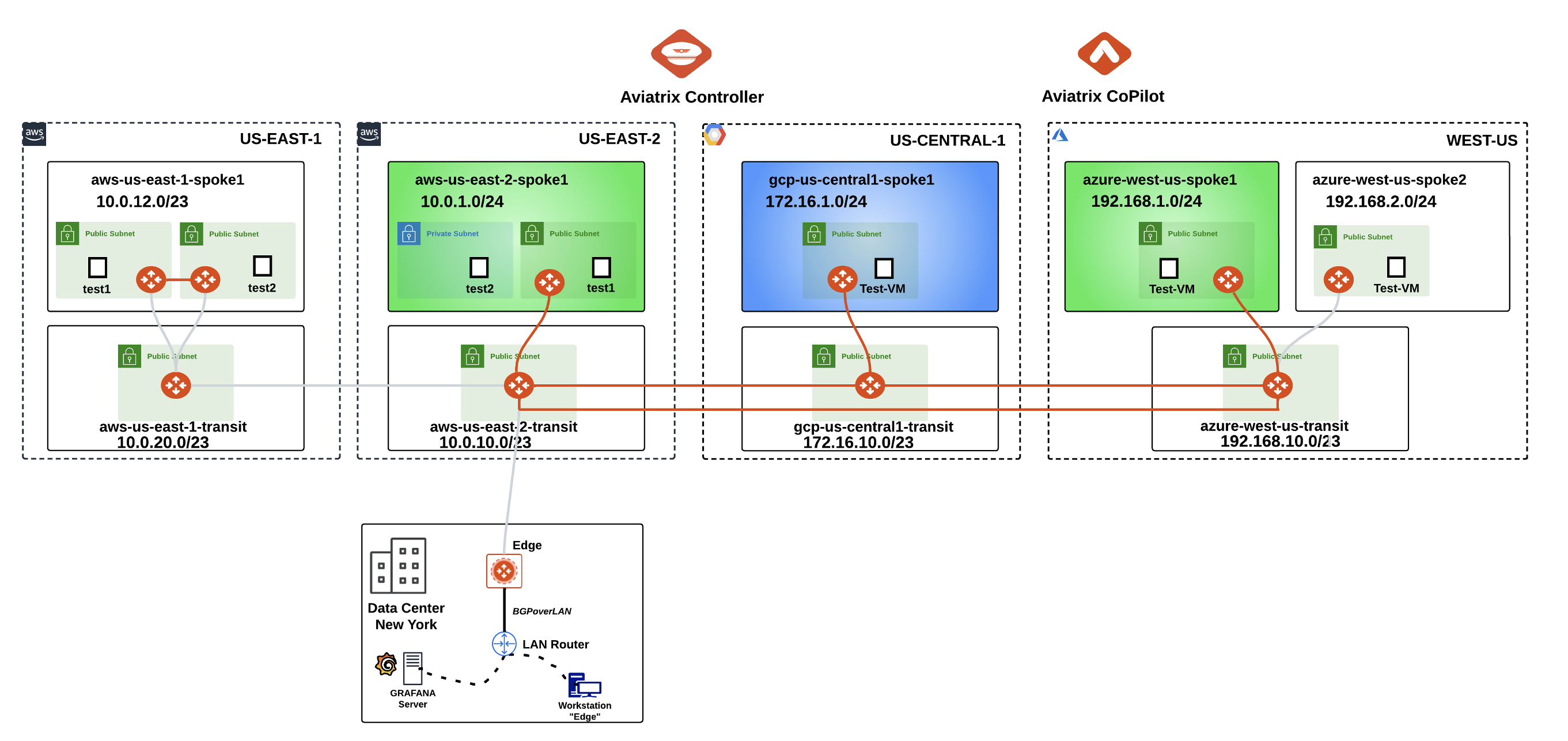
Fig. 91 Topology with Network Domains#
5. Verification of Segment Attachments#
5.1. CoPilot Verification#
Go to CoPilot > Networking > Network Segmentation > Network Domains
Verify the segments and the associations as shown below:
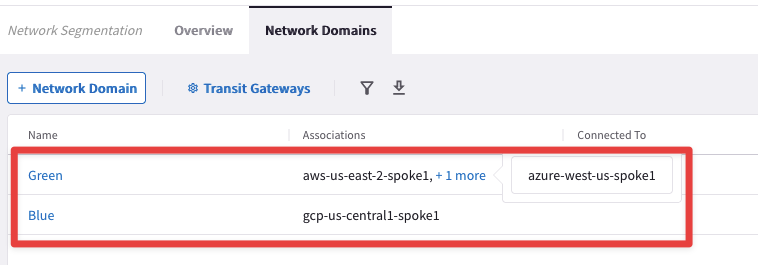
Fig. 92 Associations verification#
Go to CoPilot > Cloud Fabric > Gateways > Transit Gateways and select the Transit Gateway aws-us-east-2-transit:
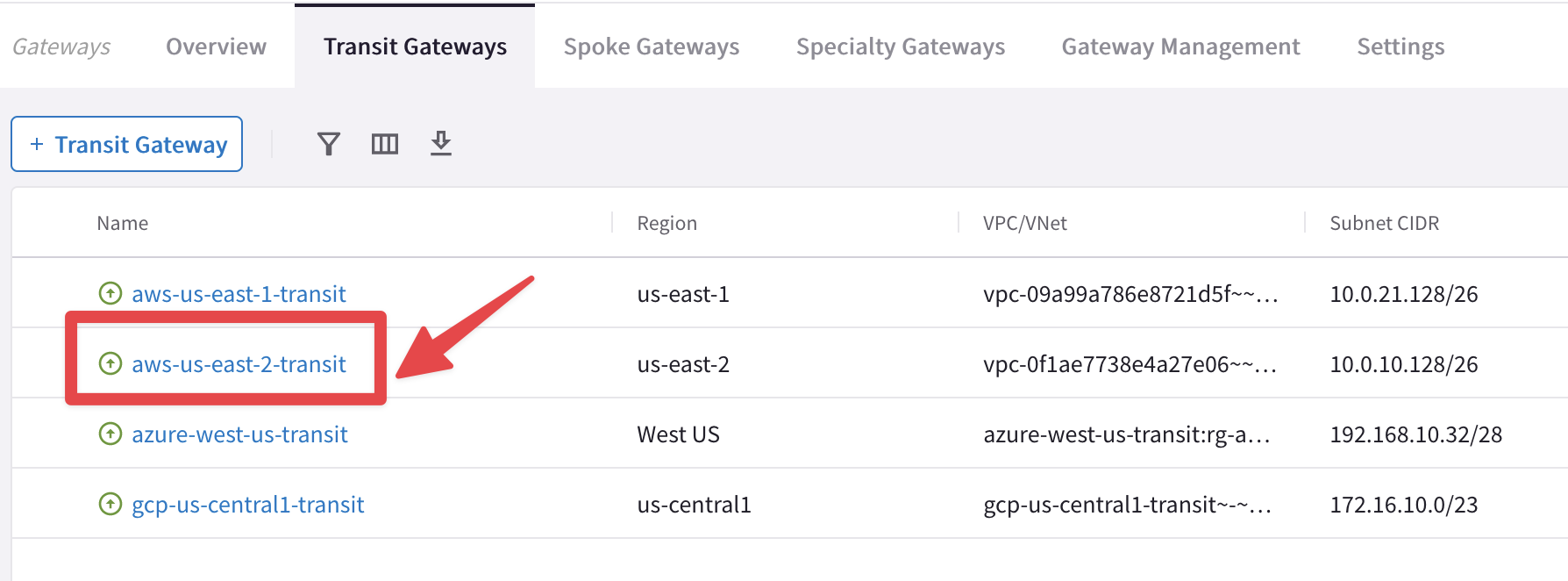
Fig. 93 Select Transit in US-East-2#
Then select the "Gateway Routes" tab and inspect the routing table of the network domain Green, likewise the routing table of the network domain Blue:
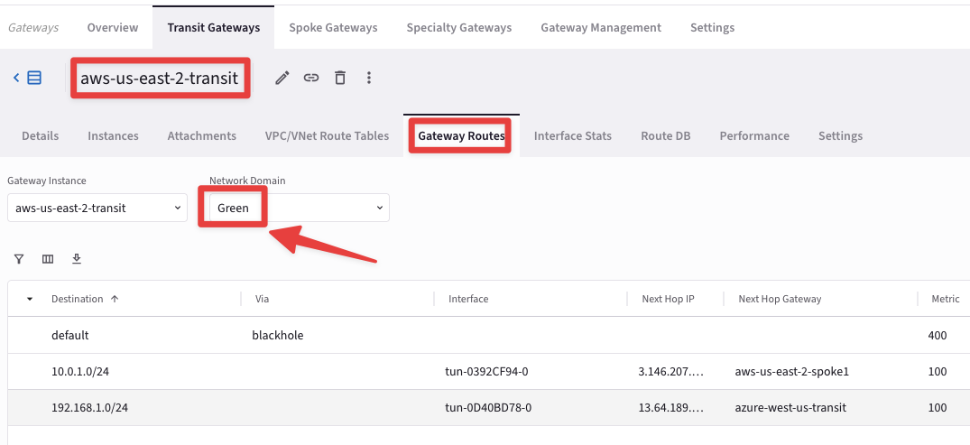
Fig. 94 Explore Green#
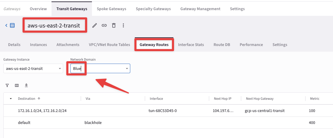
Fig. 95 Explore Blue#
Go to CoPilot > Networking > Network Segmentation > Overview > Logical View
The nodes depicted in the Logical View represent spokes and site2cloud instances. Hover over a node to highlight reachability. Nodes are grouped by colored arcs representing network domains. At this time, only the spoke gateways in Azure and AWS (i.e. Green Network Domain) are connected:
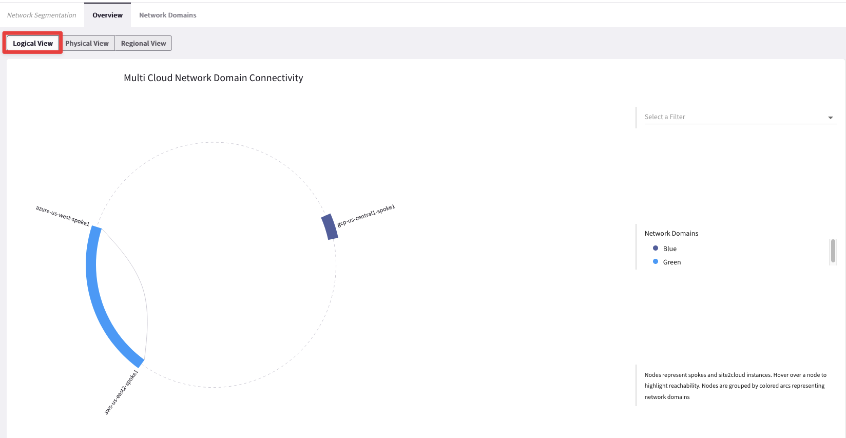
Fig. 96 Logical View#
Open three terminal windows and SSH to the test instances/VMs in each cloud and ping the private IPs of each other to test the Multicloud connectivity (Refer to pod info).
Azure and AWS resources will ping each other, but neither will be able to access GCP VM, since GCP spoke is in a different segment (Blue).
AWS:
SSH into aws-us-east-2-spoke1-test1 (ssh student@public_ip)
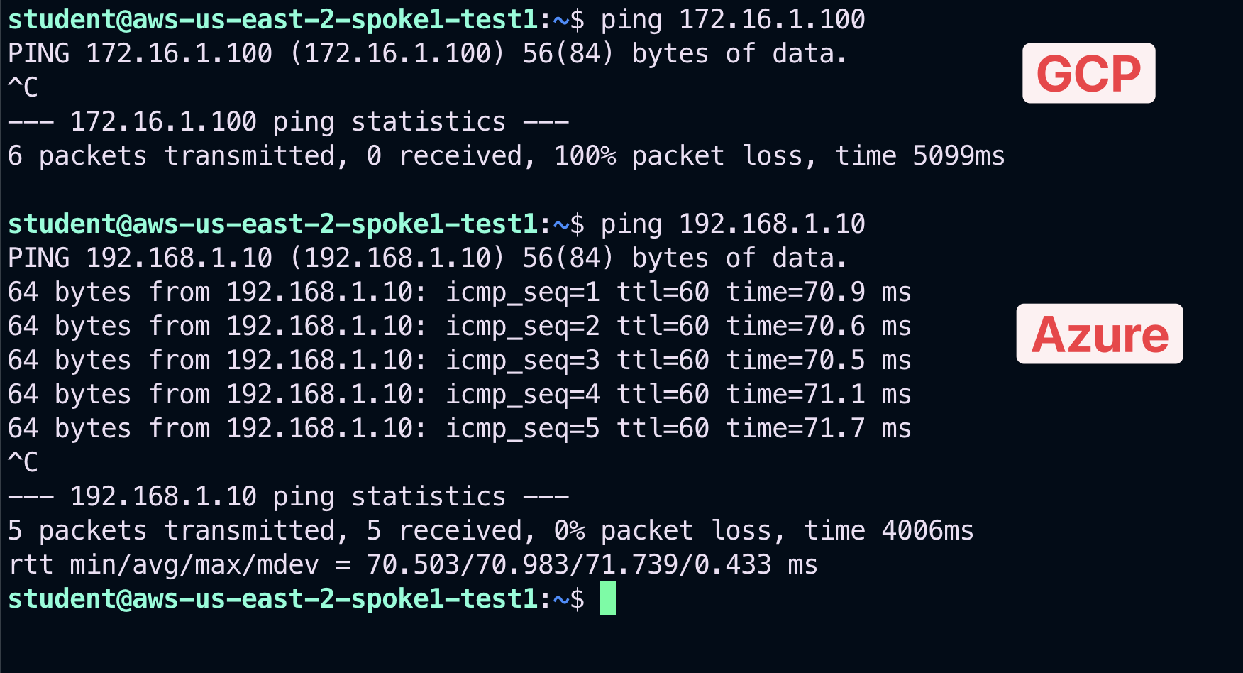
Fig. 97 Ping test from AWS#
Azure:
SSH into azure-west-us-spoke1-test1 (ssh student@public_ip)
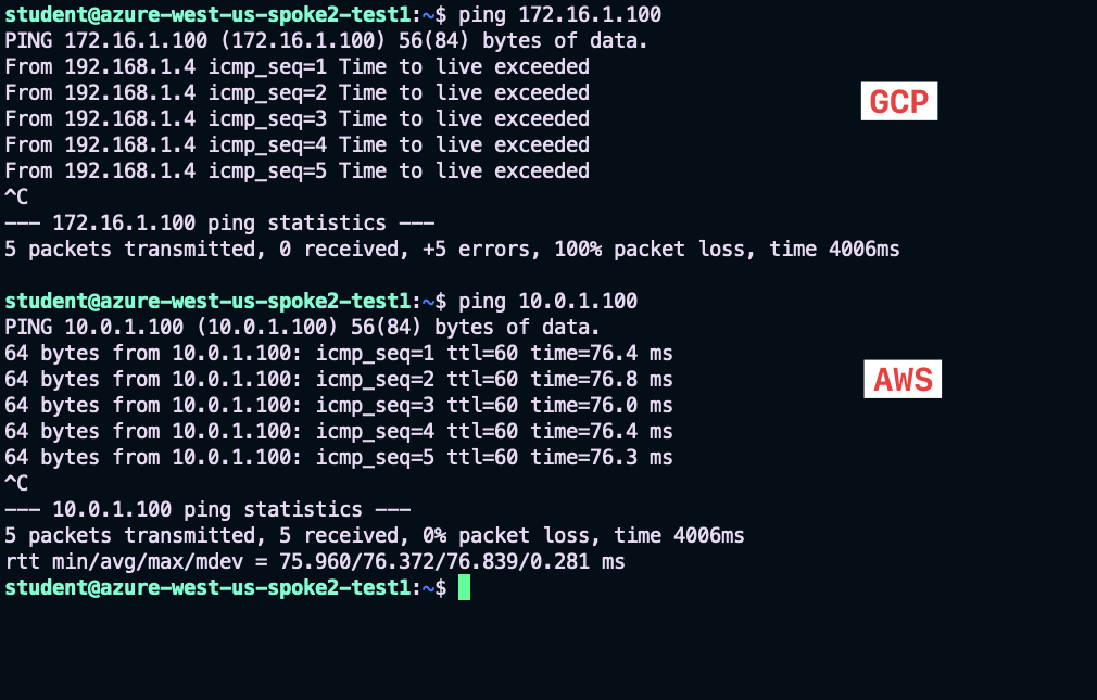
Fig. 98 Ping test from Azure#
GCP:
SSH into gcp-us-central1-spoke1-test1 (ssh student@public_ip)
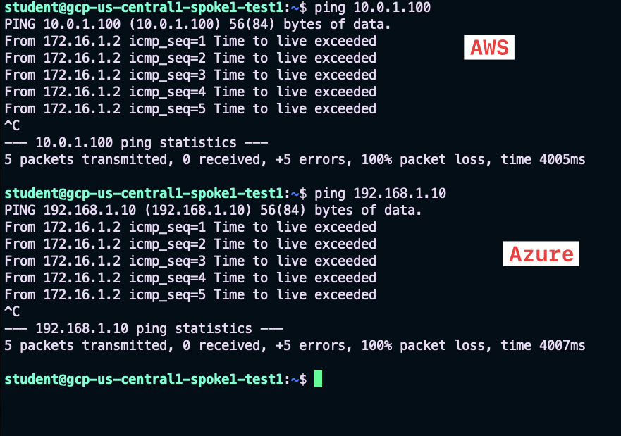
Fig. 99 Ping test from GCP#
6. Connection Policy#
Go to CoPilot > Networking > Network Segmentation > Network Domains
Click the pencil icon to edit. You can either select the Green domain or the Blue domain.
Important
The connection policy is always bidirectional!

Fig. 100 Edit Blue#
Select the appropriate option from the "Connect to Network Domain" pull-down menu (Green shown here). Then click Save:
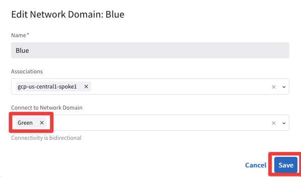
Fig. 101 Apply the Connection Policy#
6.1. Verification of Connection Policy#
Go to CoPilot > Networking > Network Segmentation > Overview > Logical View
Now you will see that the spoke gateways in all three clouds are connected. This is because the Blue and Green Network Domains are directly connected:
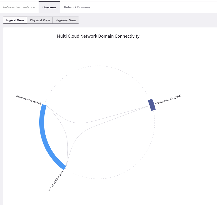
Fig. 102 Logical View with the connection policy#
Retest the connectivity; now you will have end-to-end connectivity across the multicloud environment.
AWS:
SSH into aws-us-east-2-spoke1-test1 (ssh student@public_ip)
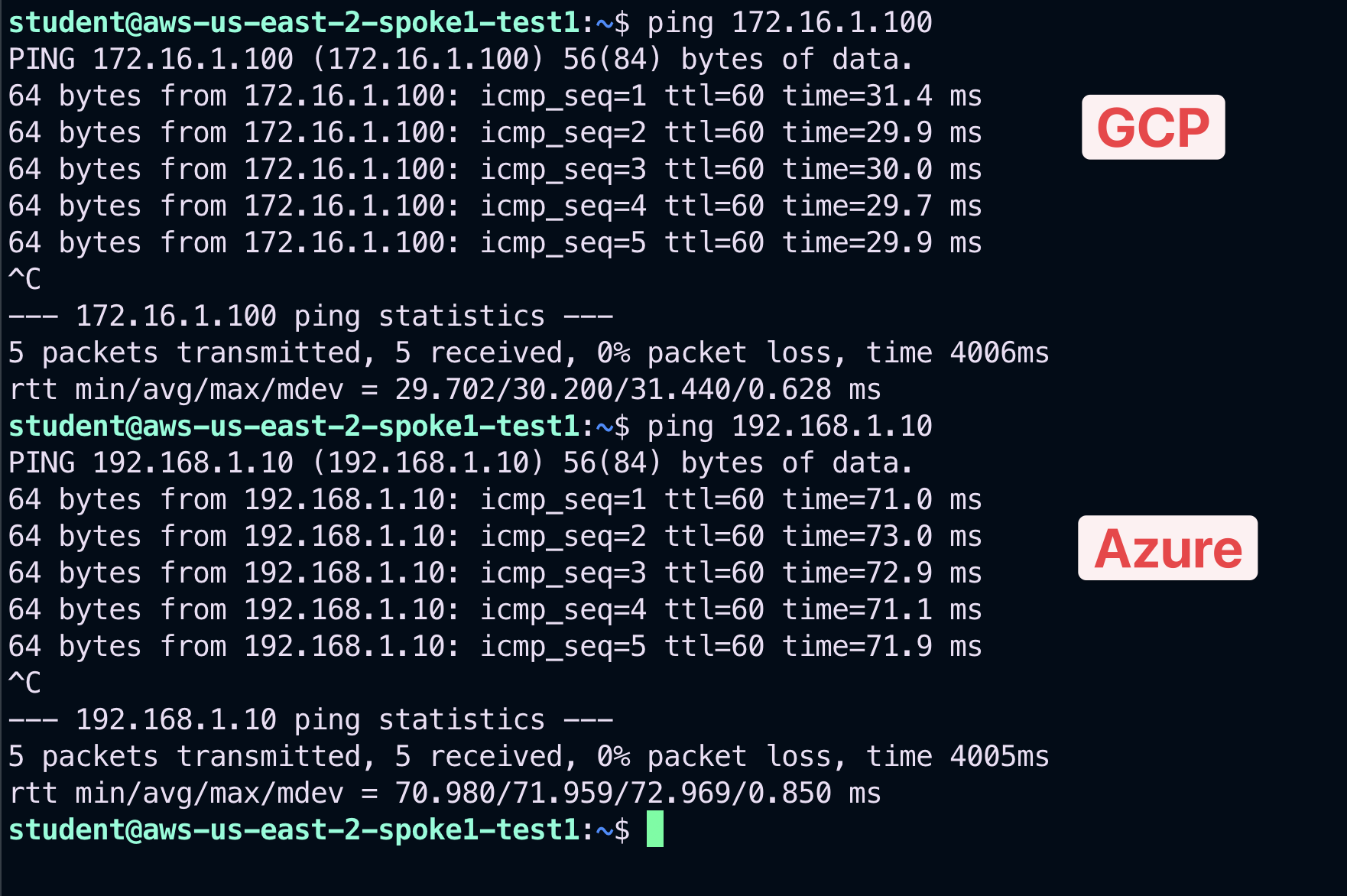
Fig. 103 New Test from AWS#
Azure:
SSH into azure-us-west-spoke1-test1 (ssh student@public_ip)
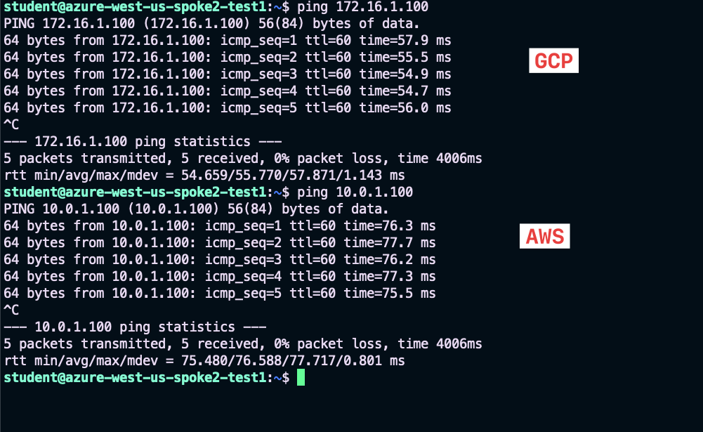
Fig. 104 New Test from Azure#
GCP:
SSH into gcp-us-central1-spoke1-test1 (ssh student@public_ip)
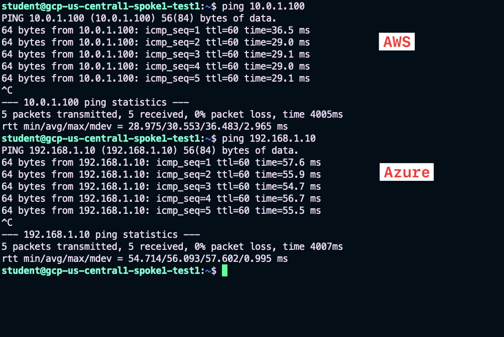
Fig. 105 New Test from GCP#
After this lab, this is how the overall topology would look like:
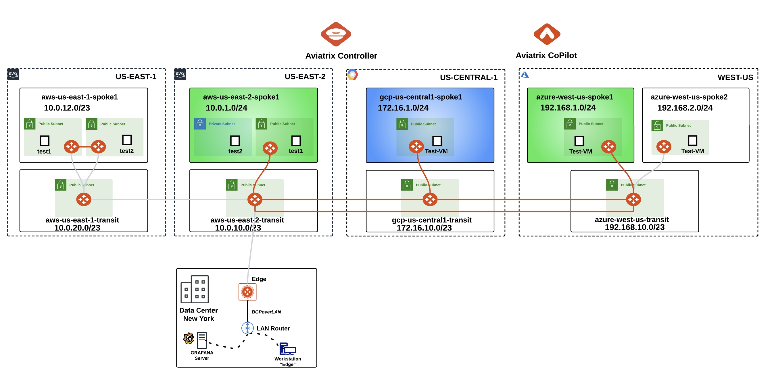
Fig. 106 Final topology for Lab 3#
