Lab 10 - DISTRIBUTED CLOUD FIREWALL#
1. Objective#
This lab will demonstrate how the Distributed Cloud Firewall works.
2. Distributed Cloud Firewall Overview#
The Distributed Cloud Firewall functionality encompases several services, such as Distributed Firewalling, Threat Prevention, TLS Decryption, URL Filtering, Suricata IDS/IPS and Advanced NAT capabilities.
In this lab you will create additional logical containers, called Smart Groups, that group instances that present similarities inside a VPC/VNet/VCN, and then you will enforce rules among these Smart Groups (aka Distributed Cloud Firewalling Rules):
intra-rule= Rule applied within a Smart Groupinter-rule= Rule applied among Smart Groups
Note
At this point in the lab, there is a unique routing domain (i.e. a Flat Routing Domain), due to the connection policy applied in Lab 3, between the Green domain and the Blue domain.
All the Test instances have been deployed with the typical CSP tags.
Important
The CSP tagging is the recommended method for defining the SmartGroups.
In this lab you are asked to achieve the following requirements among the instances deployed across the three CSPs:
Create a Smart Group with the name
"bu1"leveraging the tag"environment".Create a Smart Group with the name
"bu2"leveraging the tag"environment".Create an
intra-rulethat allows ICMP traffic within bu1.Create an
intra-rulethat allows ICMP traffic within bu2.Create an
intra-rulethat allows SSH traffic within bu1.Create an
inter-rulethat allows ICMP traffic only from bu2 to bu1.
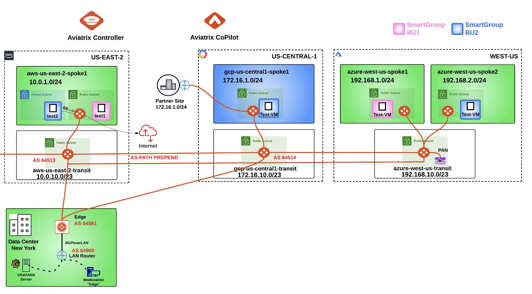
Fig. 356 Initial Topology Lab 10#
3. Smart Groups Creation#
Create two Smart Groups and classify each Smart Group, leveraging the CSP tag "environment":
Assign the name
"bu1"to the Smart Group #1.Assign the name
"bu2"to the Smart Group #2.
3.1. Smart Group “bu1”#
Go to CoPilot > Groups > SmartGroups and click on "+ SmartGroup".
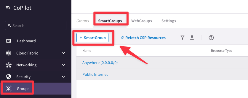
Fig. 357 SmartGroup#
Ensure these parameters are entered in the pop-up window "Create SmartGroup":
Name: bu1
CSP Tag Key: environment
CSP Tag Value: bu1
Before clicking on SAVE, discover what instances match the condition, turning on the knob "Preview".
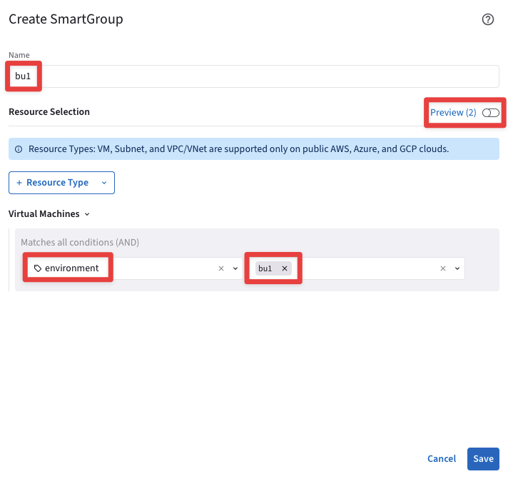
Fig. 358 Resource Selection#
The CoPilot shows that there are two instances that perfectly match the condition:
aws-us-east2-spoke1-test1 in AWS
azure-us-west-spoke1-test1 in Azure
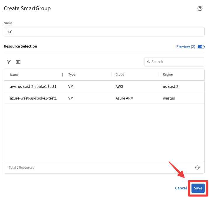
Fig. 359 Resources that match the condition#
3.2. Smart Group “bu2”#
Create another Smart Group clicking on the "+ SmartGroup" button.
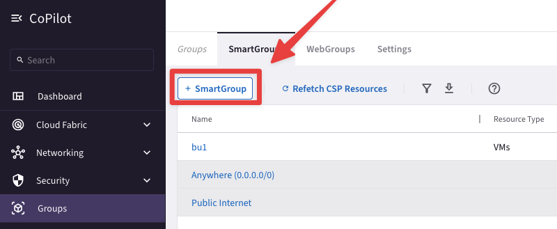
Fig. 360 New Smart Group#
Ensure these parameters are entered in the pop-up window "Create SmartGroup":
Name: bu2
CSP Tag Key: environment
CSP Tag Value: bu2
Before clicking on SAVE, discover what instances match the condition, turning on the knob "Preview".
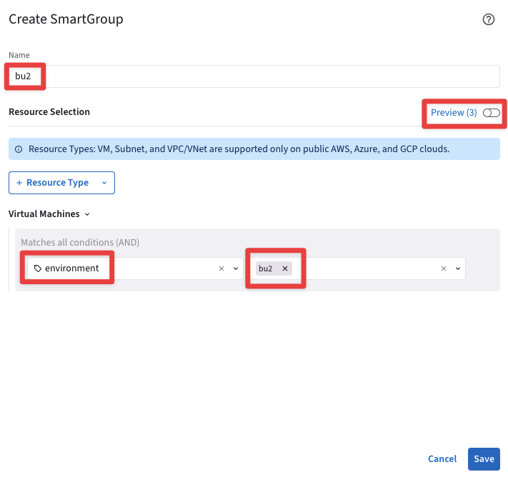
Fig. 361 Resource Selection#
The CoPilot shows that there are three instances that match the condition:
aws-us-east2-spoke1-test2 in AWS
azure-us-west-spoke2-test1 in Azure
gcp-us-central1-spoke1-test1 in GCP
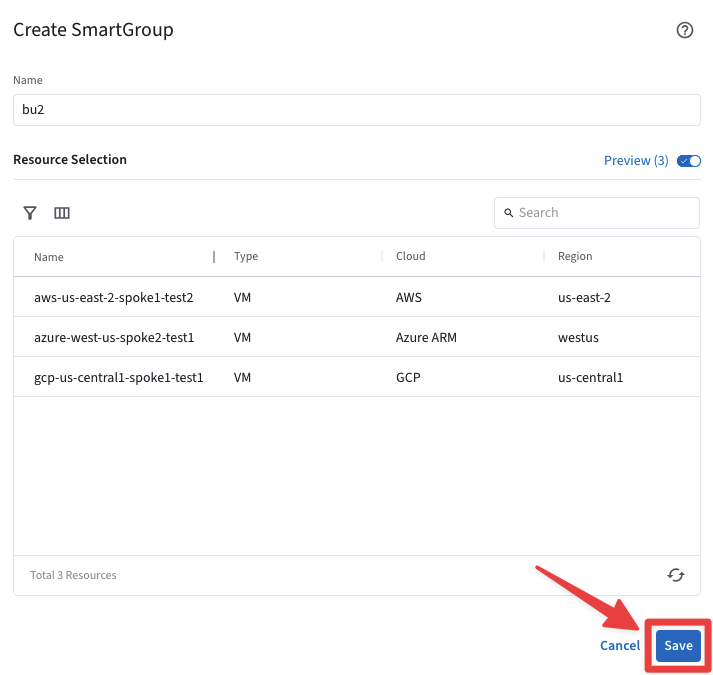
Fig. 362 Resources that match the condition#
At this point, you have only created logical containers that do not affect the existing routing domain.
Let’s verify that everything has been kept unchanged! Bear in mind that there is the Greenfield-Rule at the very top of your DCF rules list, whereby all kind of traffic will be permitted.
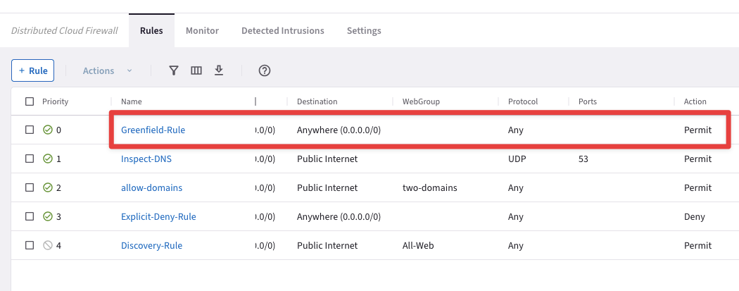
Fig. 363 Greenfield-Rule in action#
3.3. Connectivity verification (ICMP)#
Open a terminal window and SSH to the public IP of the instance aws-us-east-2-spoke1-test1 (NOT test2), and from there ping the private IPs of each other instances to verify that the connectivity has not been modified.
Note
Refer to your POD for the private IPs.
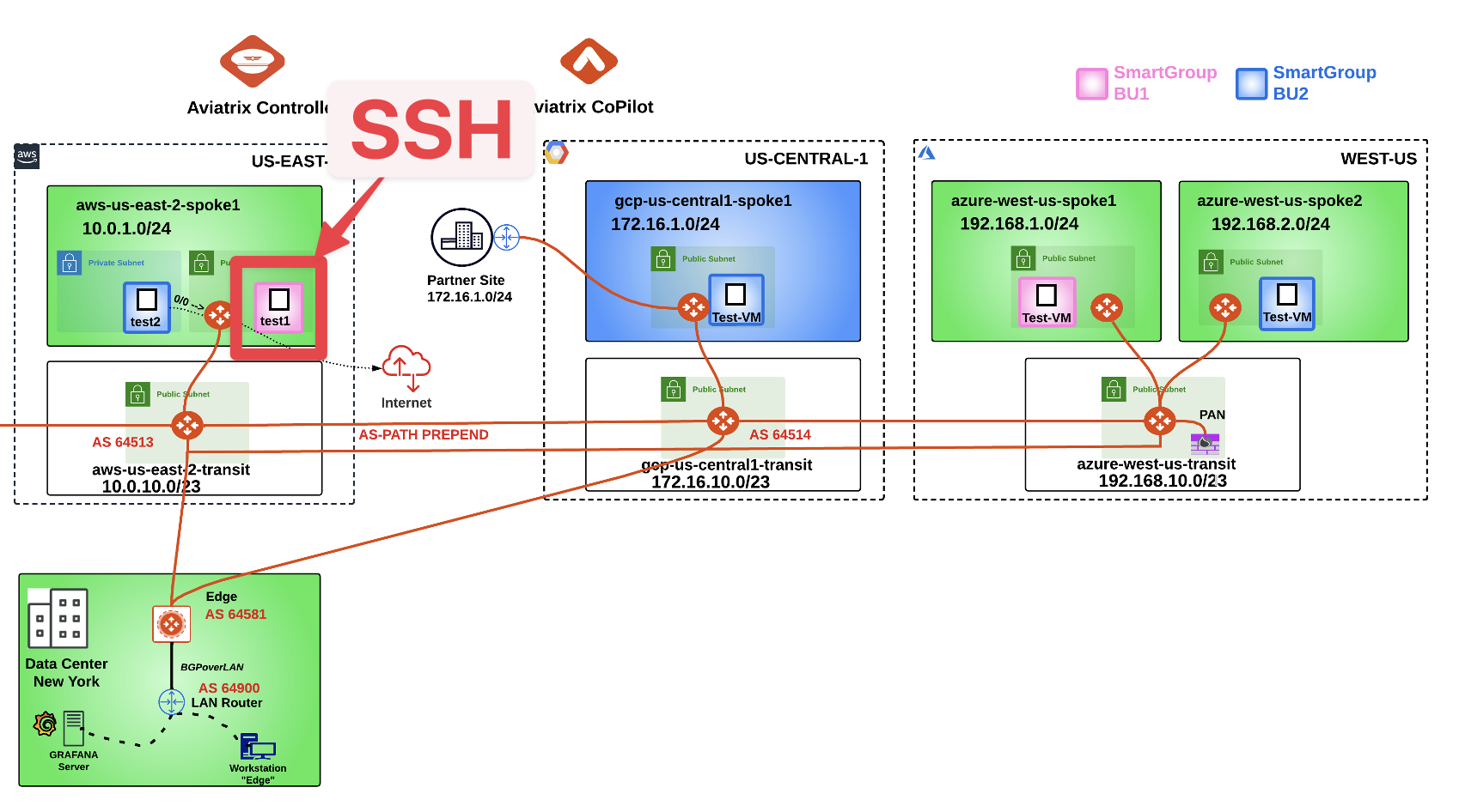
Fig. 364 SSH#
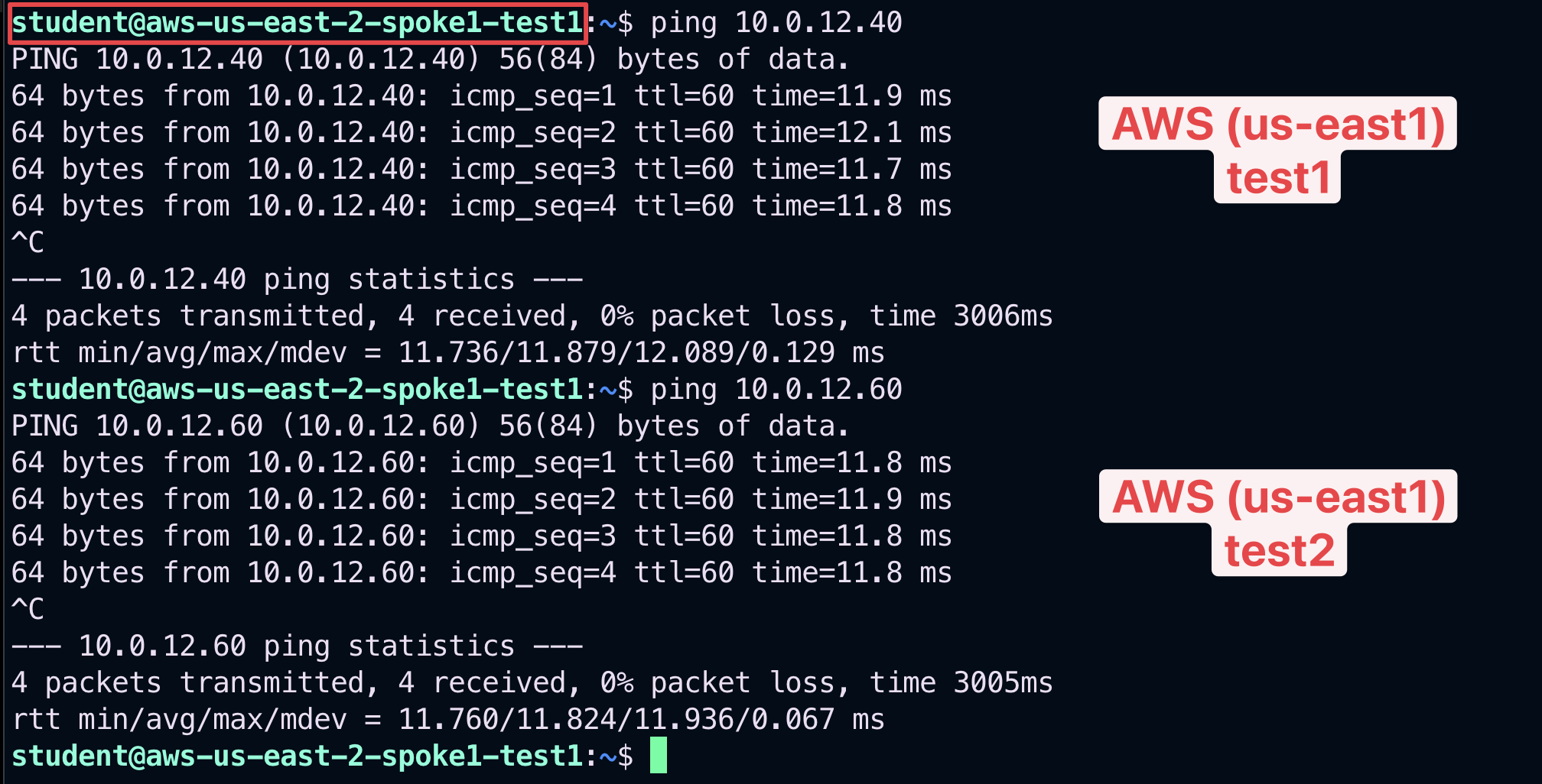
Fig. 365 Ping#
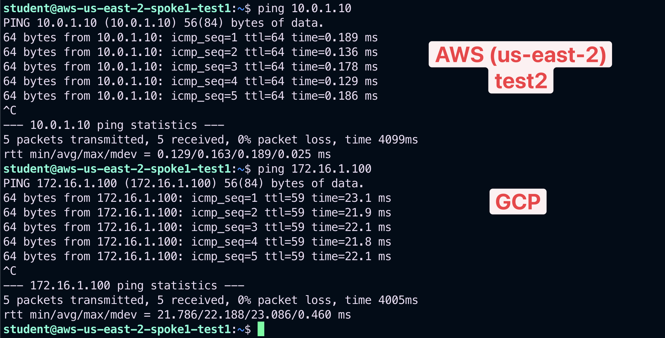
Fig. 366 Ping#
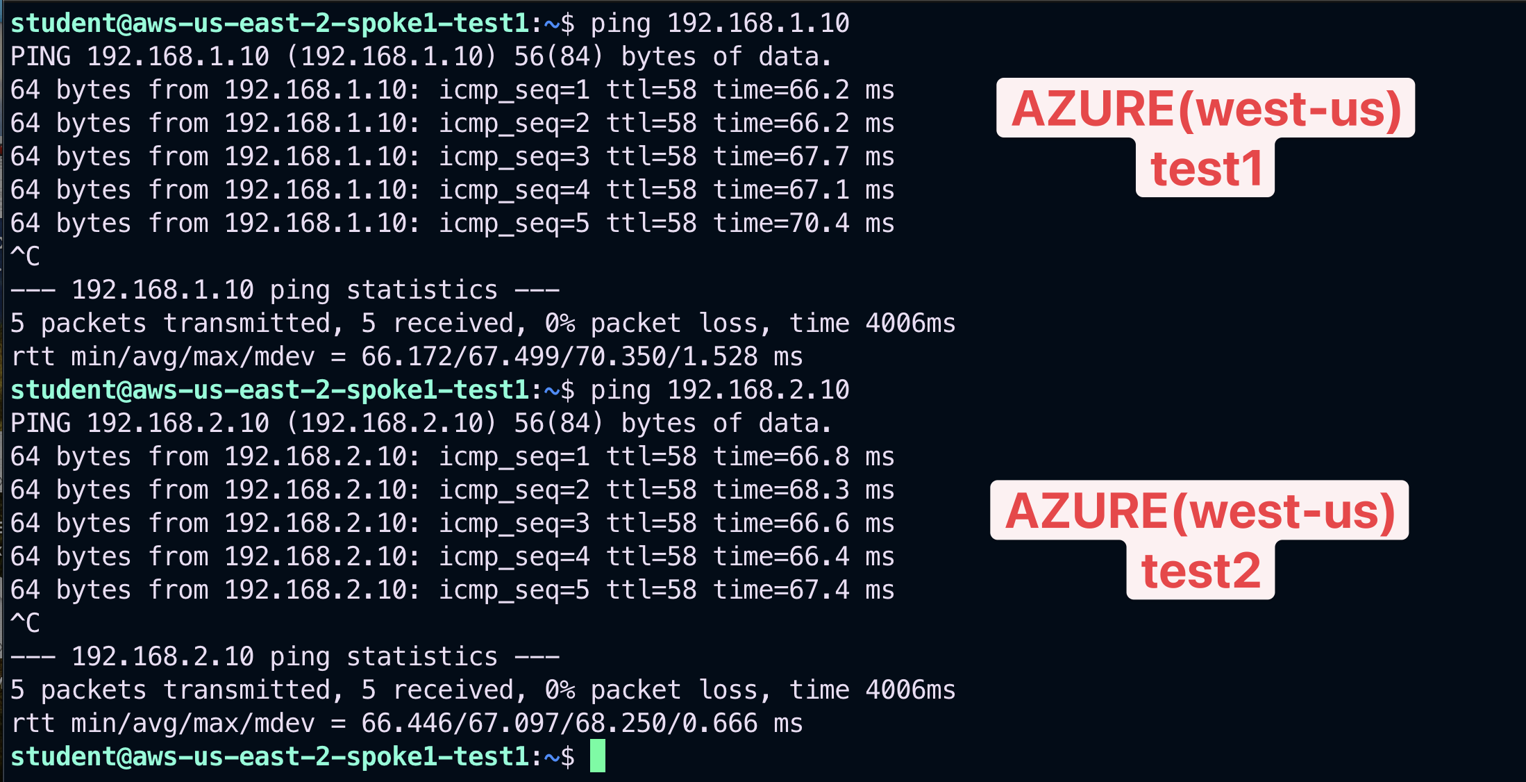
Fig. 367 Ping#
3.4. Connectivity verification (SSH)#
Verify also from the instance aws-us-east-2-spoke1-test1 that you can SSH to the private instance in AWS (us-east-2), to the instance in GCP, to the instances in AWS (us-east-2) and likewise to the other two instances in Azure.
Note
Refer to your POD for the private IPs.
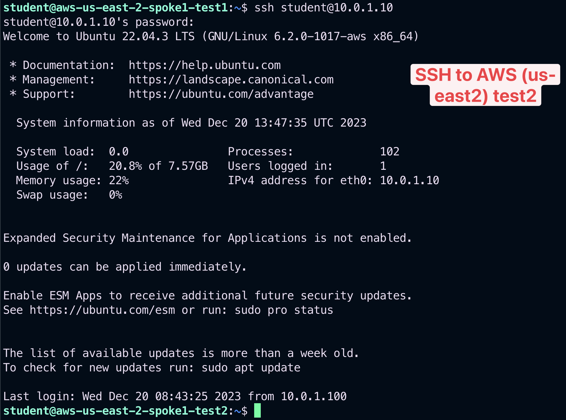
Fig. 368 SSH to test2 in AWS US-East-2#
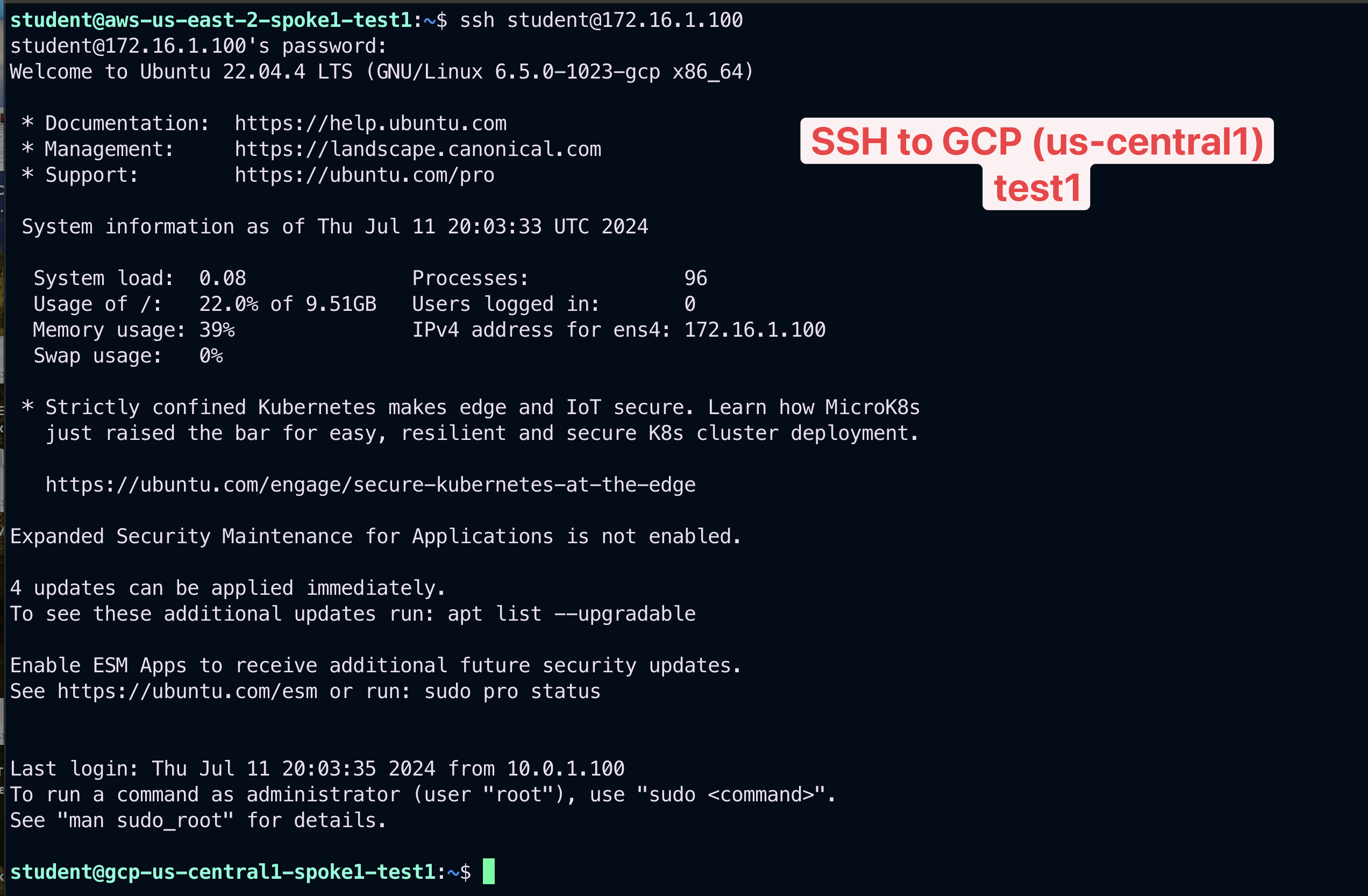
Fig. 369 SSH to test1 in GCP US-Central1#
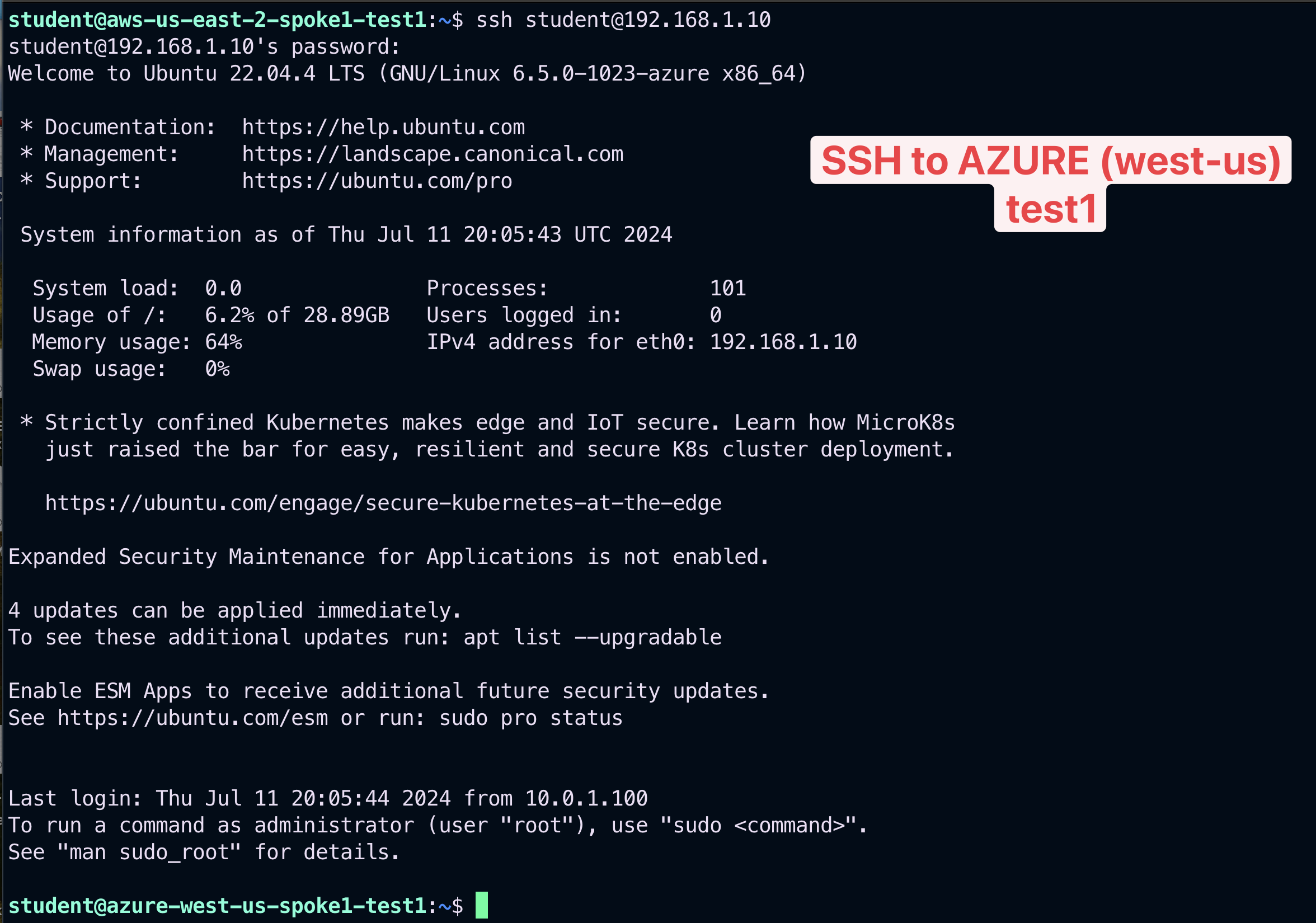
Fig. 370 SSH to test1 in Azure West-US#
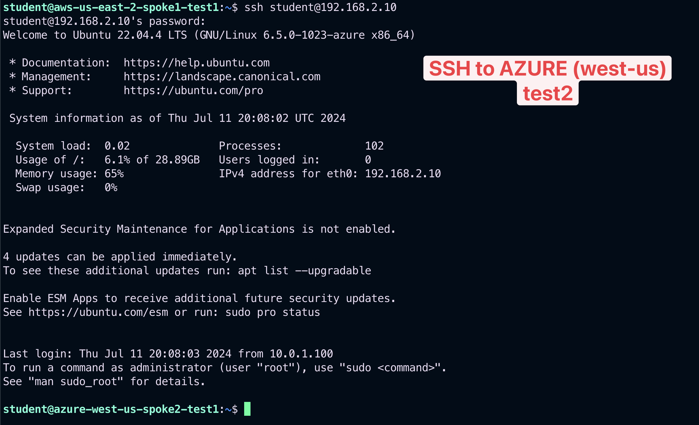
Fig. 371 SSH to test2 in Azure West-US#
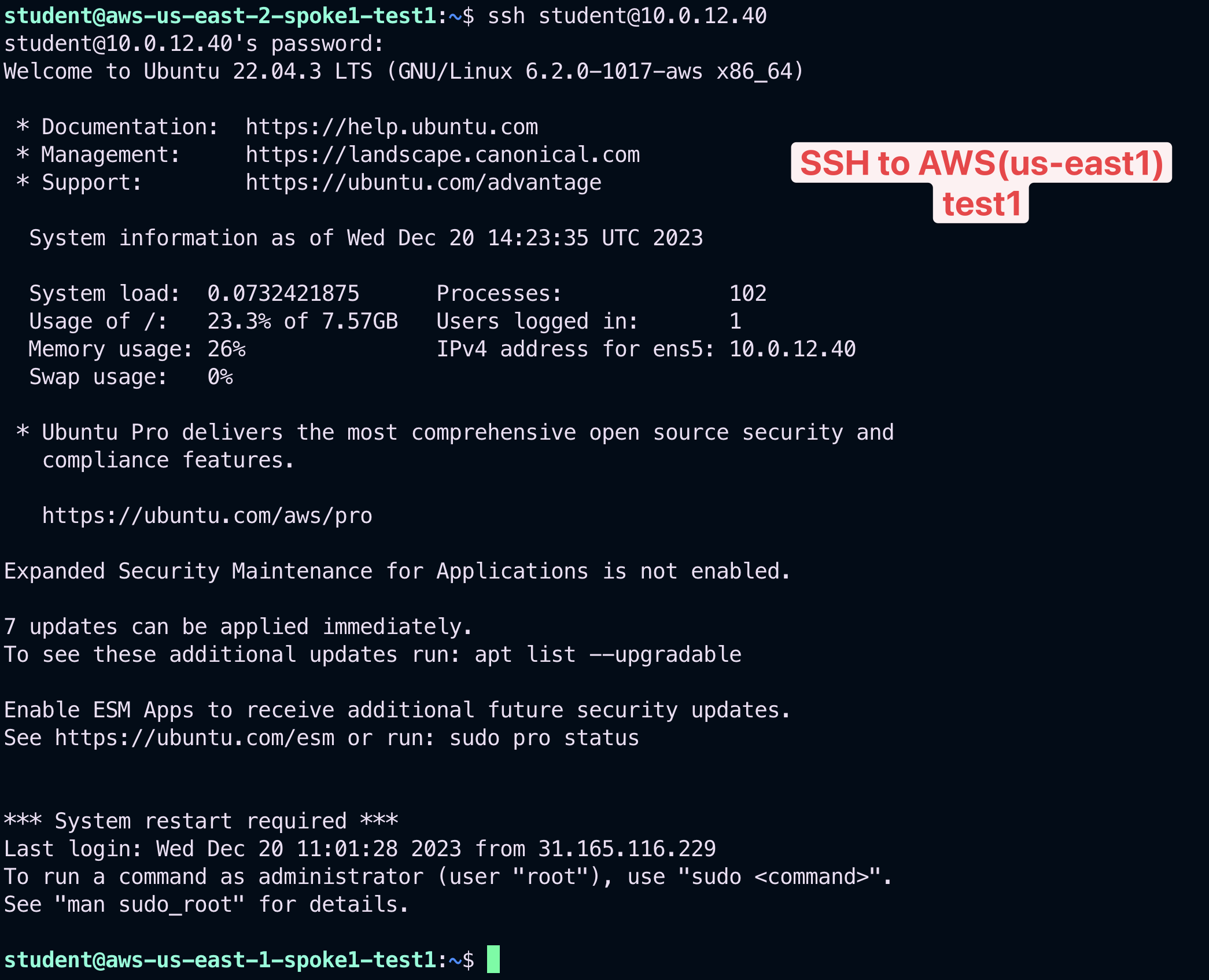
Fig. 372 SSH to test1 in AWS US-East1#
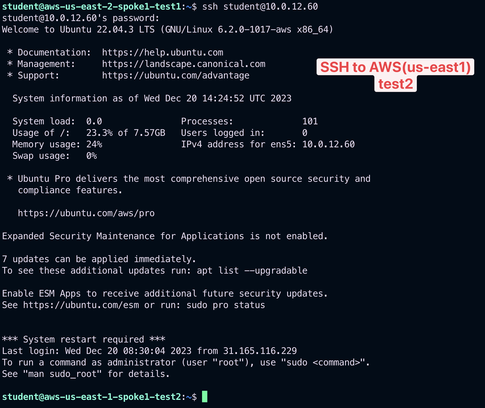
Fig. 373 SSH to test2 in AWS US-East1#
The previous outcomes confirm undoubtetly that the connectivity is working smoothly, despite the creation of those two new Smart Groups.
4. DCF Rules Creation#
4.1. Build a Zero Trust Network Architecture#
First and foremost, let’s move the Explicit-Deny-Rule at the very top of the list of your DCF rules.
Tip
Go to CoPilot > Security > Distributed Cloud Firewall > Rules (default), click on the the "two arrows" icon on the righ-hand side of the Explicit-Deny-Rule and choose "Move Rule" at the very Top.
Then click on Save in Draft.

Fig. 374 Move the rule#
Then Commit your change!

Fig. 375 Commit#
Warning
Zero Trust architecture is “Never trust, always verify”, a critical component to enterprise cloud adoption success!
4.2. Create an intra-rule that allows ICMP inside bu1#
Go to CoPilot > Security > Distributed Cloud Firewall > Rules (default tab) and create a new rule clicking on the "+ Rule" button.
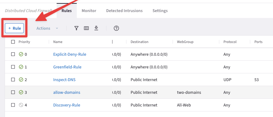
Fig. 376 New Rule#
Insert the following parameters:
Name: intra-icmp-bu1
Source Smartgroups: bu1
Destination Smartgroups: bu1
Protocol: ICMP
Logging: On
Action: Permit
Do not forget to click on Save In Drafts.
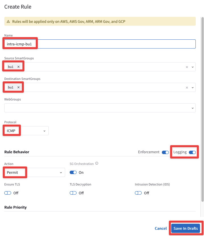
Fig. 377 Create Rule#
At this point, there should be just one uncommitted rule at the very top, as depicted below.
Click on Commit.
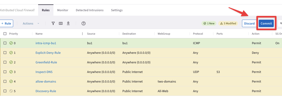
Fig. 378 Current list of rules#
4.2. Create an intra-rule that allows ICMP inside bu2#
Create another rule clicking on the "+ Rule" button.
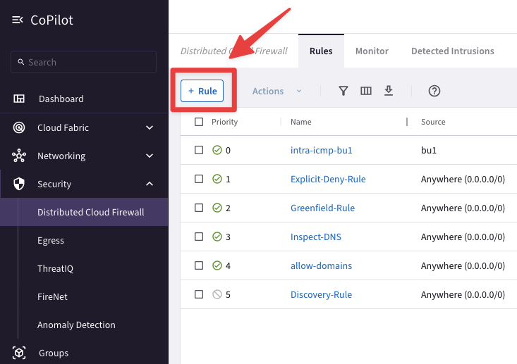
Fig. 379 New rule#
Ensure these parameters are entered in the pop-up window "Create Rule":
Name: intra-icmp-bu2
Source Smartgroups: bu2
Destination Smartgroups: bu2
Protocol: ICMP
Logging: On
Action: Permit
Place Rule: Below
Existing Rule: intra-icmp-bu1
Do not forget to click on Save In Drafts.
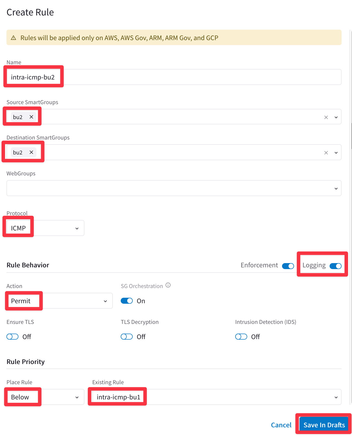
Fig. 380 intra-icmp-bu2#
At this point, you will have one new rule marked as New, therefore you can proceed and click on the Commit button.
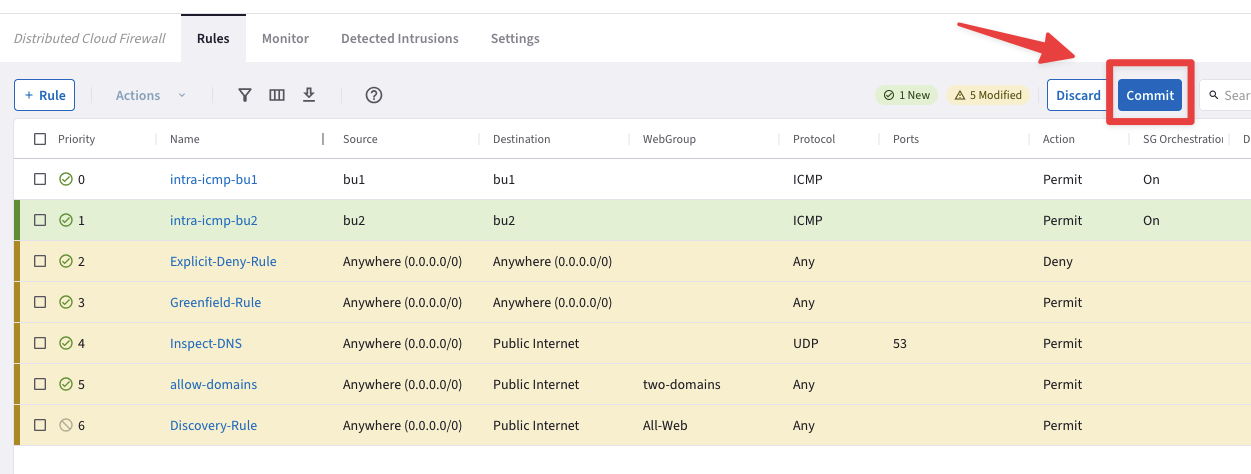
Fig. 381 Commit#
5. Verification#
Afte the creation of the previous Smart Groups and Rules, this is how the topology with the permitted protocols should look like:
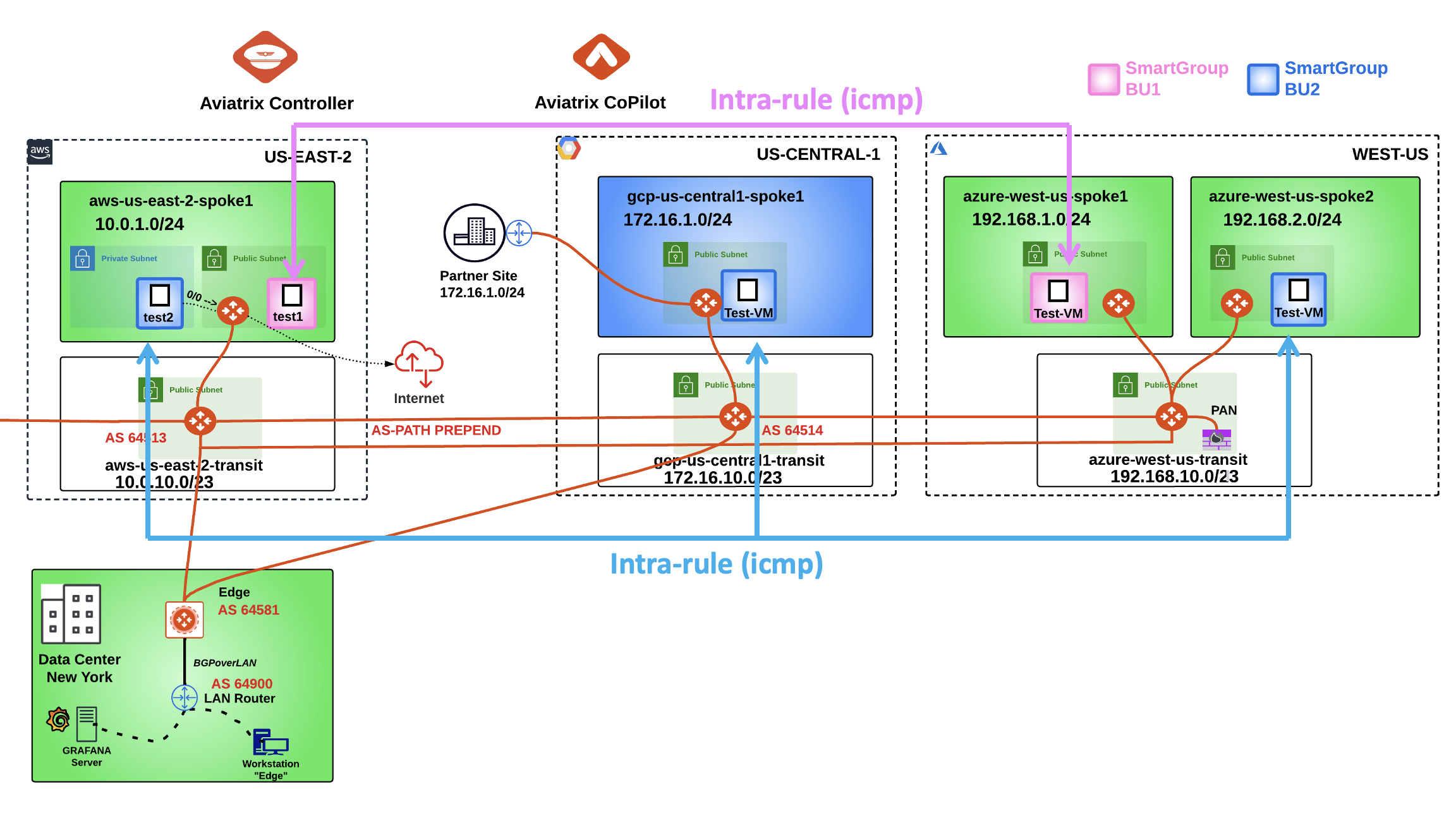
Fig. 382 New Topology#
5.1. Verify SSH traffic from your laptop to bu1#
SSH to the Public IP of the instance aws-us-east-2-spoke1-test1.
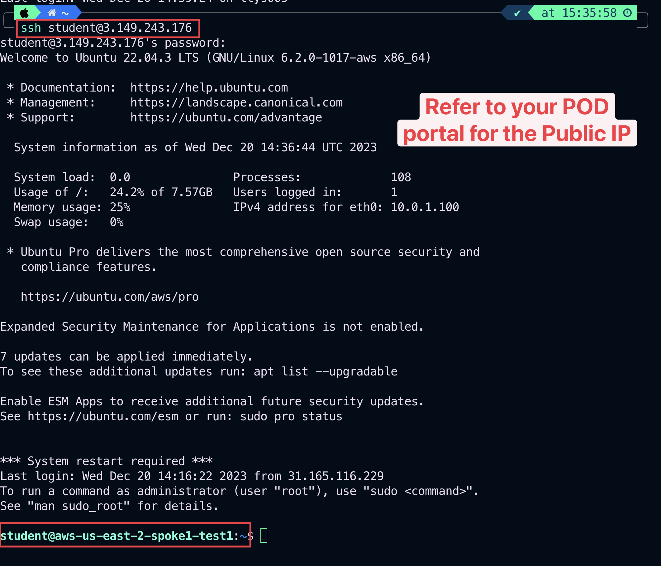
Fig. 383 SSH from your laptop#
5.2. Verify ICMP within bu1 and from bu1 towards bu2#
Ping the following instances from aws-us-east-2-spoke1-test1:
gcp-us-central1-spoke1-test1 in GCP
azure-west-us-spoke1-test1 in Azure
azure-west-us-spoke2-test1 in Azure
According to the rules created before, only the ping towards the azure-us-west-spoke1-test1 will work, because this instance belongs to the same Smart Group bu1 as the instance from where you generated ICMP traffic.
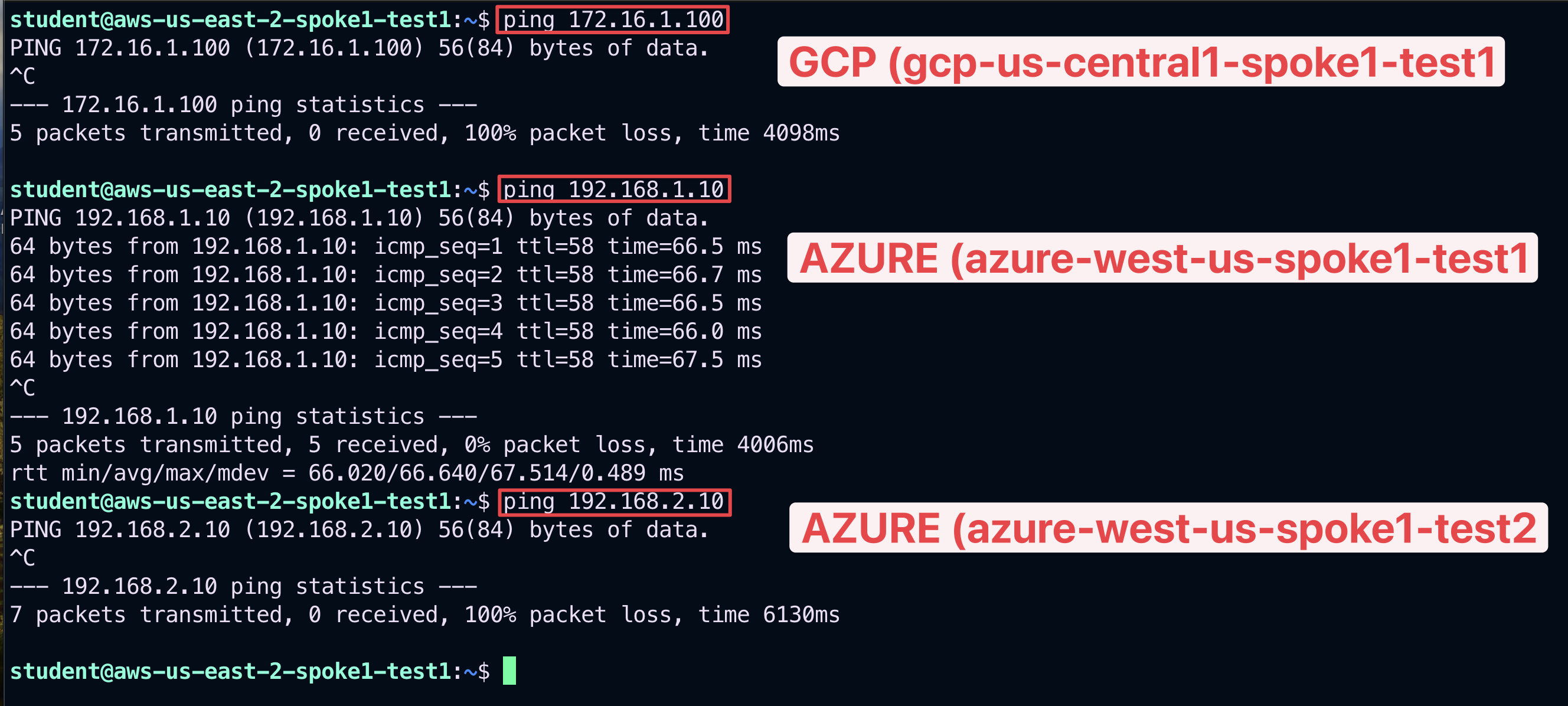
Fig. 384 Ping#
Let’s investigate the logs:
Go to CoPilot > Security > Distributed Cloud Firewall > Monitor
Tip
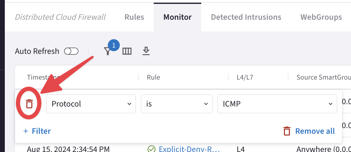
Turn on the Auto Refresh knob. Moreover, refresh the web page to trigger the logs. You can also filter out based on the protocol ICMP.
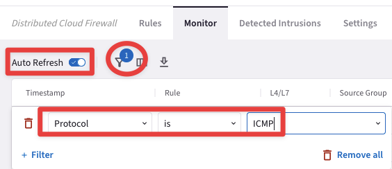
Fig. 385 Auto Refresh and Filter#

Fig. 386 Monitor#
Now, let’s try to ping the instance aws-us-east-2-spoke1-test2 from aws-us-east-2-spoke1-test1.
Warning
The instance aws-us-east-2-spoke1-test1 is in the same VPC. Although these two instances have been deployed in two distinct and separate Smart Groups, the communication will occur until you don’t enable the "Security Group(SG) Orchestration" (aka intra-vpc separation).

Fig. 387 Ping#
Go to CoPilot > Security > Distributed Cloud Firewall > Settings and click on the "Manage" button, inside the "Security Group (SG) Orchestration" field.
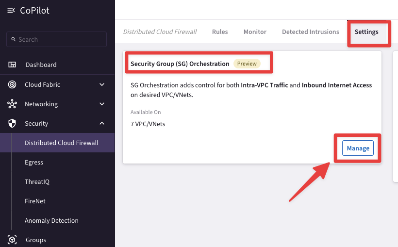
Fig. 388 SG Orchestration#
Enable the SG orchestration feature on the aws-us-east-2-spoke1 VPC, flag the checkbox "I understand the network impact of the changes" and then click on Save.
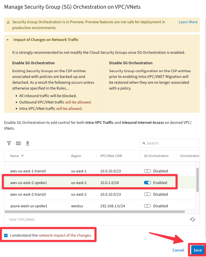
Fig. 389 Manage SG Orchestration#
Relaunch the ping from aws-us-east-2-spoke1-test1 towards aws-us-east-2-spoke1-test2.

Fig. 390 Ping fails#
Important
This time the ping fails. You have achieved a complete separation between Smart Groups deployed in the same VPC in AWS US-EAST-2, thanks to the Security Group Orchestration carried out by the Aviatrix Controller.
5.3. Verify SSH within bu1#
SSH to the Private IP of the instance azure-west-us-spoke1-test1 in Azure. Despite the fact that the instance is within the same Smart Group “bu1”, the SSH will fail due to the absence of a rule that would permit SSH traffic within the Smart Group.

Fig. 391 SSH fails#
5.4. Add a rule that allows SSH in bu1#
Create another rule clicking on the "+ Rule" button.
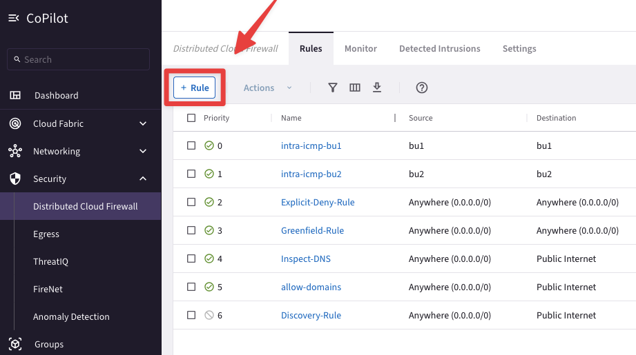
Fig. 392 New rule#
Ensure these parameters are entered in the pop-up window "Create Rule":
Name: intra-ssh-bu1
Source Smartgroups: bu1
Destination Smartgroups: bu1
Protocol: TCP
Port: 22
Logging: On
Action: Permit
Place Rule: Below
Existing Rule: intra-icmp-bu2
Do not forget to click on Save In Drafts.
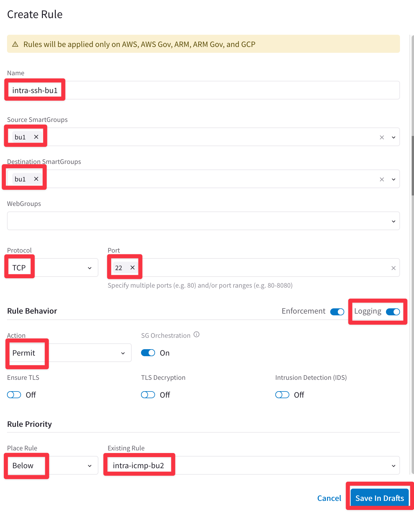
Fig. 393 Create rule#
Click on "Commit" to enforce the new rule in the Data Plane.
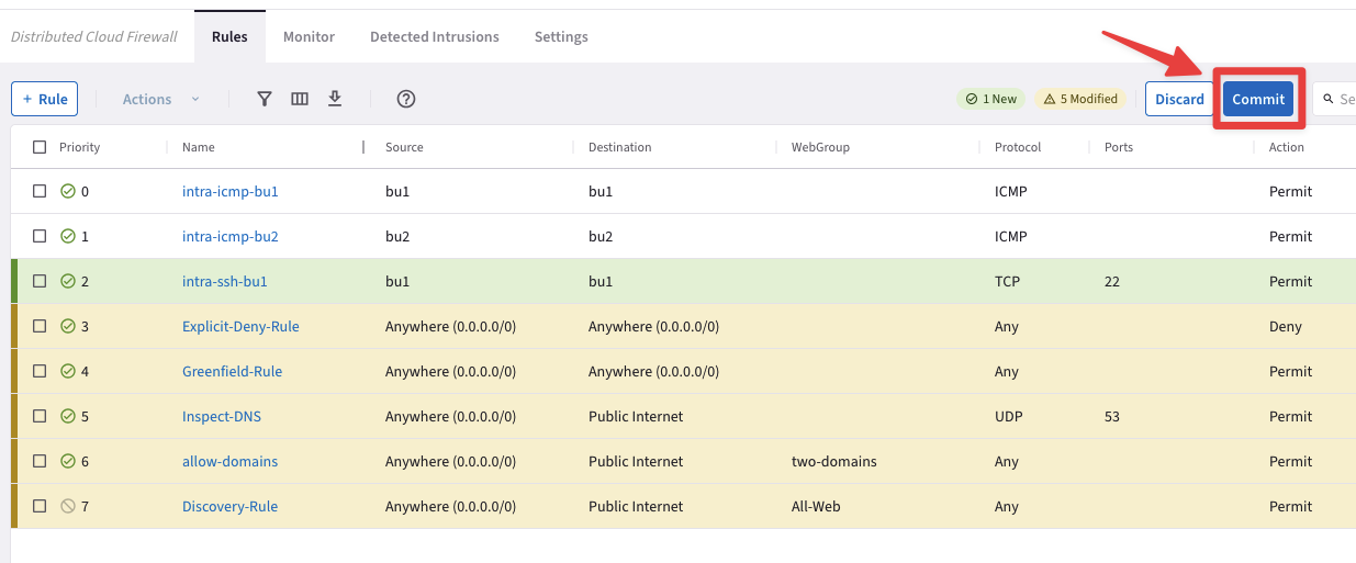
Fig. 394 Commit#
Try once again to SSH to the Private IP of the instance azure-west-us-spoke1-test1 in Azure in BU1.
This time the connection will be established, thanks to the new intra-rule.
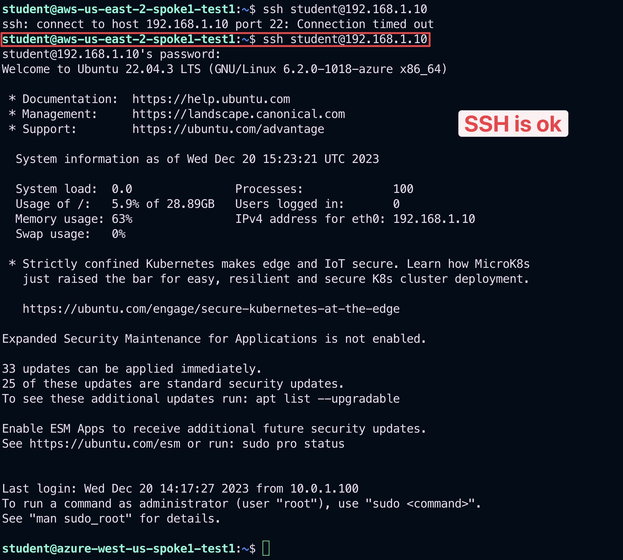
Fig. 395 SSH ok#
Let’s investigate the logs once again.
Go to CoPilot > Security > Distributed Cloud Firewall > Monitor
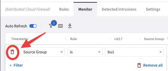
Now set a new filter based on the parameters showed in the screenshot below:
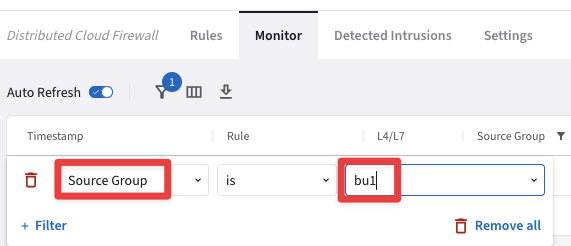
Fig. 397 Source Group = bu1#

Fig. 398 Logs#
From the log above is quite evident that the "intra-ssh-bu1” rule is permitting SSH traffic within the Smart Group bu1, successfully.
After the creation of the previous intra-rule, this is how the topology with the permitted protocols should look like:
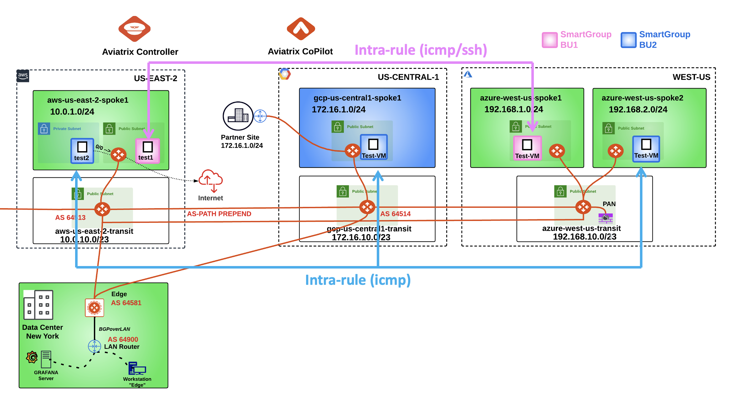
Fig. 399 New Topology#
5.4. SSH to VM in bu2#
SSH to the Public IP of the instance gcp-us-central1-spoke1-test1:

Fig. 400 SSH to gcp-us-central1-spoke1-test1#
5.5. Verify ICMP traffic within bu2#
Ping the following instances:
aws-us-east-2-spoke1-test1 in AWS
aws-us-east-2-spoke1-test2 in AWS
azure-west-us-spoke1-test1 in Azure
azure-west-us-spoke2-test1 in Azure
According to the rules created before, only the ping towards the azure-west-us-spoke2-test1 and aws-us-east-2-spoke1-test2 will work, because these two instance belongs to the same Smart Group bu2 as the instance from where you executed the ICMP traffic.
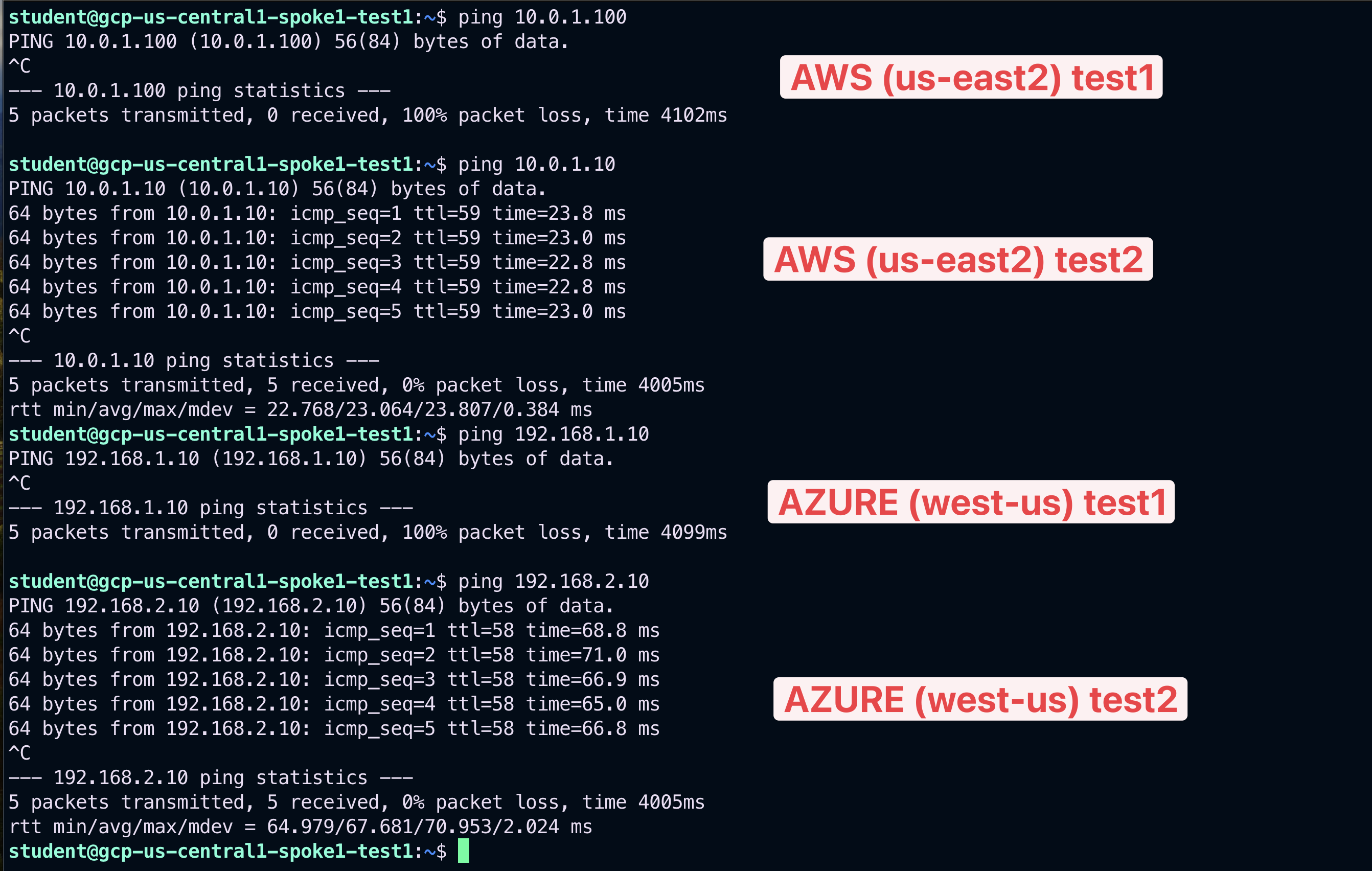
Fig. 401 Ping#
Let’s investigate the logs once again.
Go to CoPilot > Security > Distributed Cloud Firewall > Monitor

Fig. 403 Monitor#
The logs above confirm that the ICMP protocol is permitted within the Smart Group bu2.
5.6. Inter-rule from bu2 to bu1#
Create a new rule that allows ICMP FROM bu2 TO bu1.
Go to CoPilot > Security > Distributed Cloud Firewall > Rules and click on the "+ Rule" button.
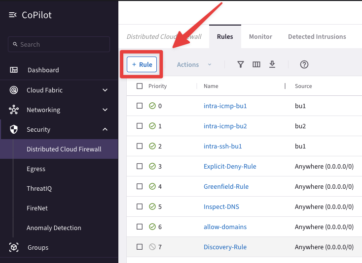
Fig. 404 New Rule#
Ensure these parameters are entered in the pop-up window "Create New Rule":
Name: inter-icmp-bu2-bu1
Source Smartgroups: bu2
Destination Smartgroups: bu1
Protocol: ICMP
Logging: On
Action: Permit
Place Rule: Below
Existing Rule: intra-ssh-bu1
Do not forget to click on Save In Drafts.
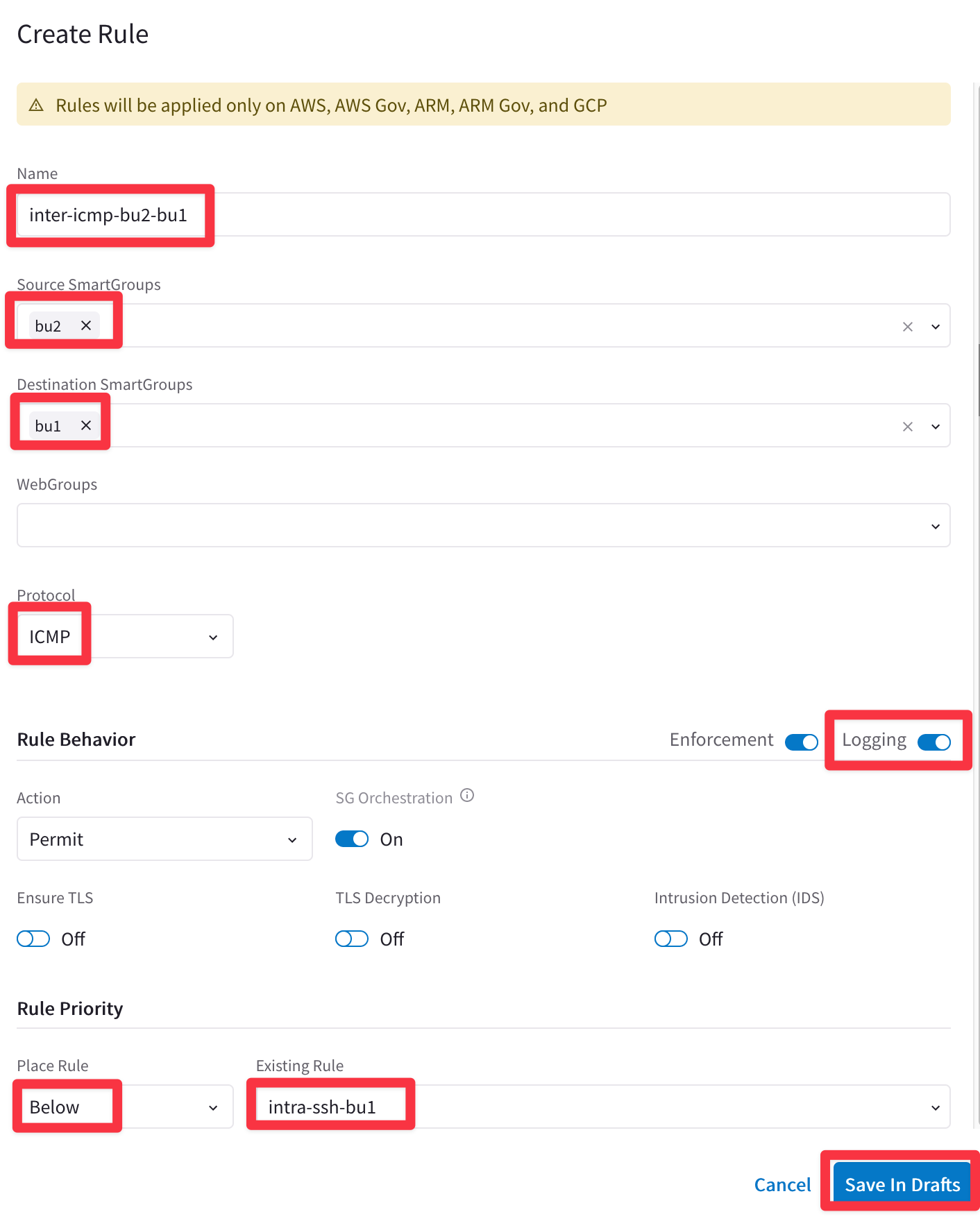
Fig. 405 Create Rule#
Enforce the this new rule in the data plane clicking on the "Commit" button.
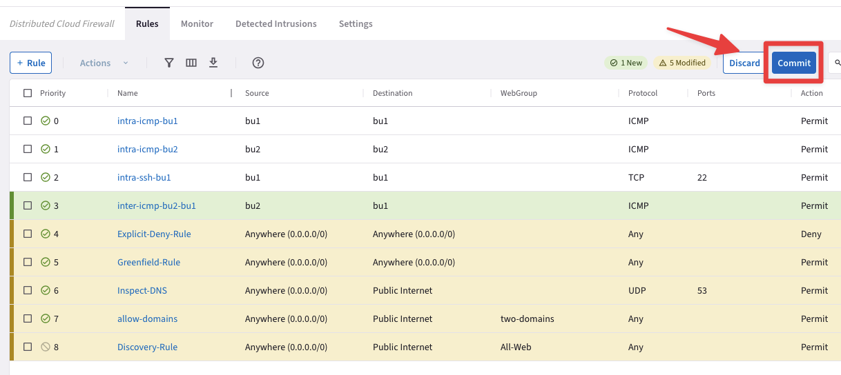
Fig. 406 Commit#
SSH to the Public IP of the instance azure-west-us-spoke2-test1.
Ping the following instances:
aws-us-east-2-spoke1-test1 in AWS
aws-us-east-2-spoke1-test2 in AWS
gcp-us-central1-spoke1-test1 in GCP
azure-west-us-spoke1-test1 in Azure
Thit time all pings will be successful, thanks to the inter-rule applied between bu2 and bu1.
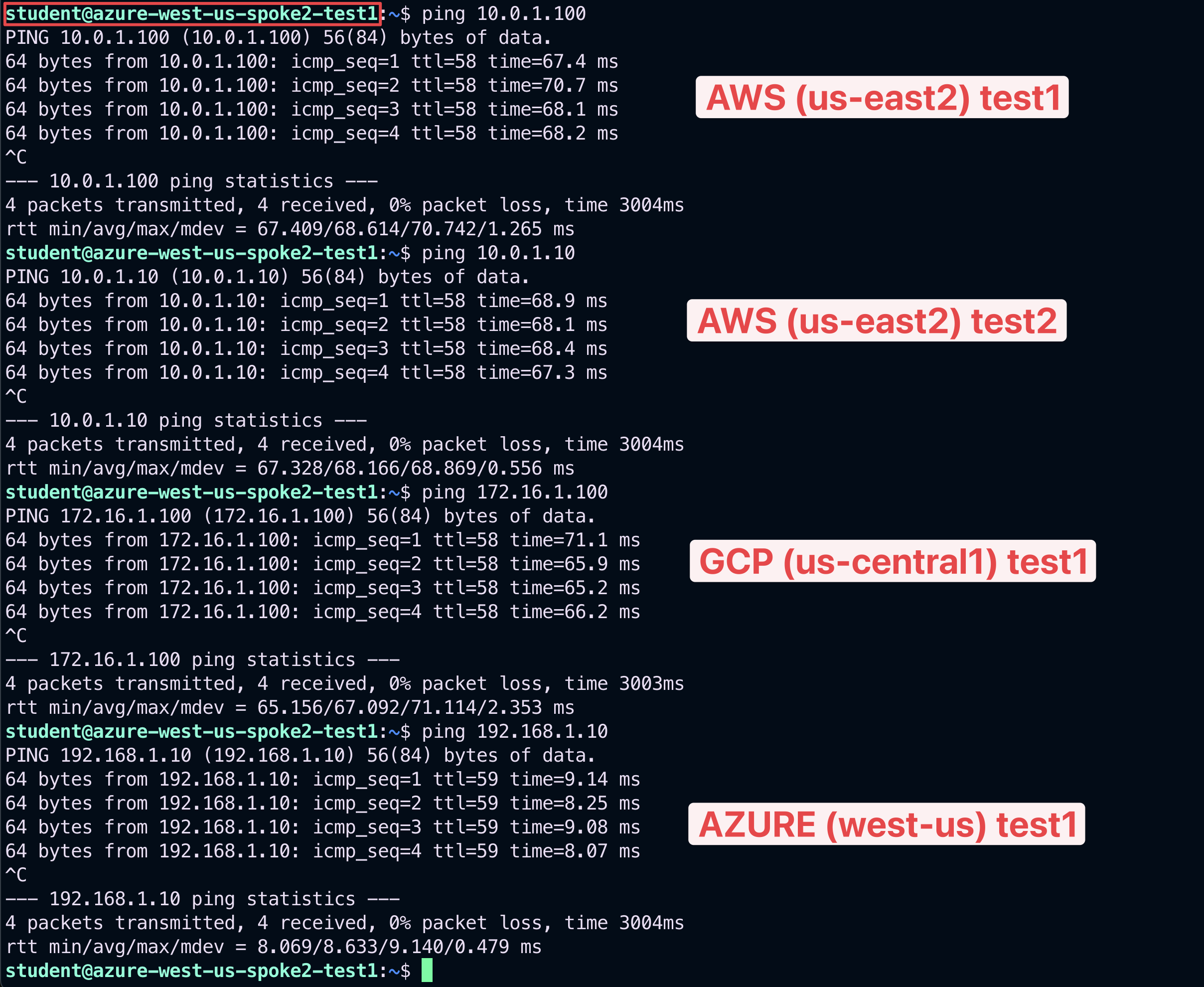
Fig. 407 Ping ok#
Let’s investigate the logs once again.
Go to CoPilot > Security > Distributed Cloud Firewall > Monitor
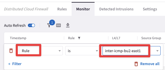
Set a new filter based on the parameters showed in the screenshot below:
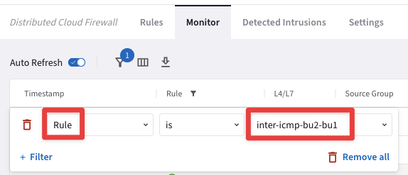
Fig. 408 Rule = inter-icmp-bu2-bu1#

Fig. 409 Monitor#
The logs clearly demonstrate that the inter-rule is successfully permitting ICMP traffic from bu2 to bu1.
After the creation of the previous inter-rule, this is how the topology with all the permitted protocols should look like.
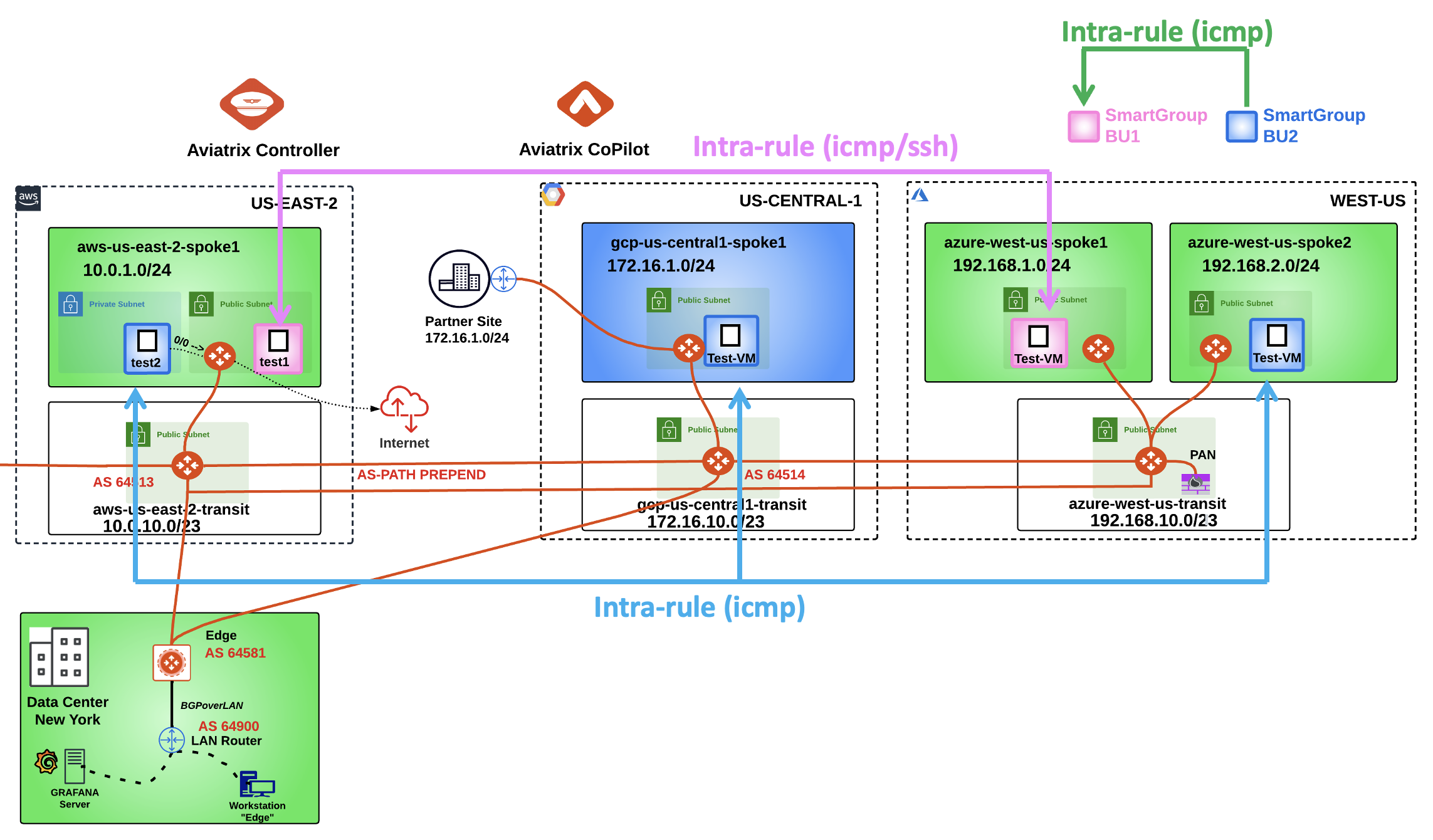
Fig. 410 New Topology with the DCF rules#
Note
The last inter-rule works smoothly only because the ICMP traffic is generated from the bu2, however, if you SSH to any instances in the Smart Group bu1, the ICMP traffic towards bu2 will fail due to the direction of the inter-rule that was created before: FROM bu2 TO bu1 (please note the direction of the arrow in the drawing).

Fig. 411 From-To#
The inter-rule is Stateful in the sense that it will permit the echo-reply generated from the bu1 to reach the instance in bu2.
6. East-1 and the Multi-Tier Transit#
6.1 Activation of the MTT#
Let’s now also involve the AWS region US-EAST-1.
This time, you have to allow the ICMP traffic between the Smart Group bu2 and the ec2 instance aws-us-east-1-spoke1-test2, solely.
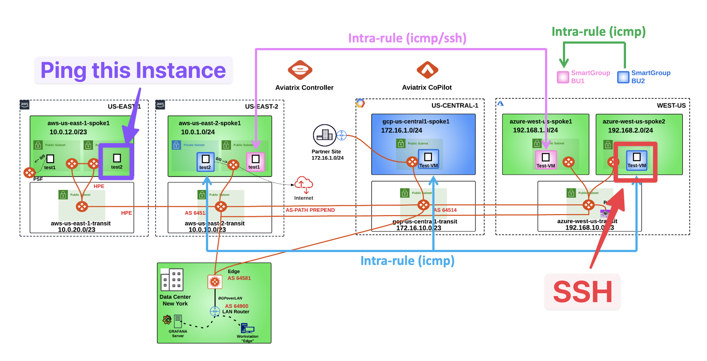
Fig. 412 New Topology#
SSH to the Public IP of the instance azure-west-us-spoke2-test1.
Ping the following instance:
aws-us-east-1-spoke1-test2 in AWS

Fig. 413 Ping#
The ping fails, therefore, let’s check the routing table of the Spoke Gateway azure-west-us-spoke2.
Go to CoPilot > Cloud Fabric > Gateways > Spoke Gateways > select the gateway azure-west-us-spoke2
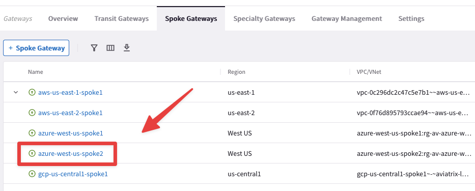
Fig. 414 azure-west-us-spoke2#
Then click on the "Gateway Routes" tab and check whether the destination route is present in the routing table or not.
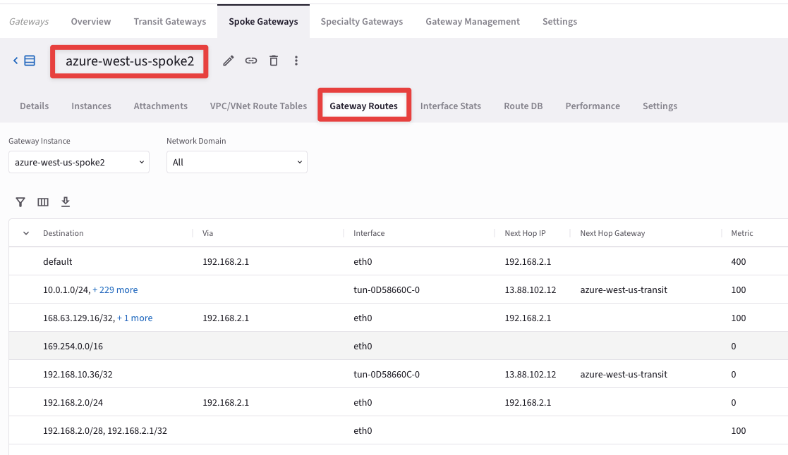
Fig. 415 Gateway Routes#
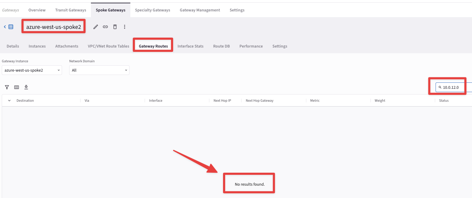
Fig. 416 10.0.12.0#
Note
The destination route is not inside the routing table, due to the fact that the Transit Gateway in AWS US-EAST-1 region has only one peering with the Transit Gateway in AWS US-EAST-2 region, therefore the Controller will install the routes that belong to US-EAST-1 only inside the routing tables of the Gateways in AWS US-EAST-2, excluding the rest of the Gateways of the MCNA. If you want to distribute the routes from AWS US-EAST-1 region in the whole MCNA, you have two possibilities:
Enabling
"Full-Mesh"on the Transit Gateways in aws-us-east1-transit VPCOR
Enabling
"Multi-Tier Transit"
Let’s enable the MTT feature, to see its beahvior in action!
Go to CoPilot > Cloud Fabric > Gateways > Transit Gateways and click on the Transit Gateway aws-us-east-1-transit.
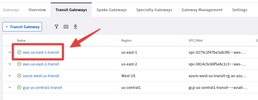
Fig. 417 aws-us-east-1-transit#
Go to "Settings" tab and expand the "“Border Gateway Protocol (BGP)” section and insert the AS number 64512 on the empty field related to the "“Local AS Number”, then click on Save.
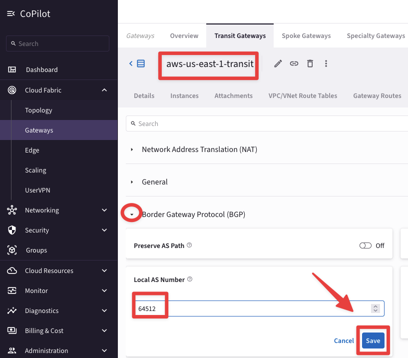
Fig. 418 Border Gateway Protocol (BGP)#
Repeat the previous action for the last Transit Gateway still without BGP ASN:
azure-west-us-transit: ASN 64515
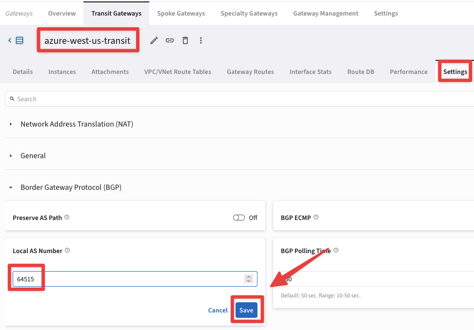
Fig. 419 azure-west-us-transit#
Note
Both the aws-us-east-2-transit and the the gcp-us-central1-transit got already configured with their ASNs during the Lab 8!
Go to CoPilot > Cloud Fabric > Gateways > Transit Gateways and click on the Transit Gateway aws-us-east-2-transit.
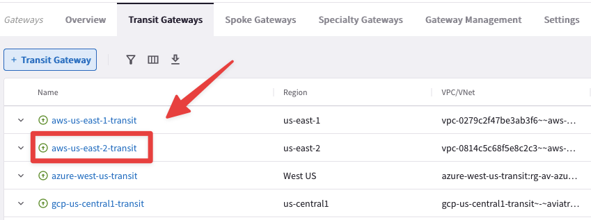
Fig. 420 aws-us-east-2-transit#
Go to "Settings" tab and expand the "General" section and activate the "Multi-Tier Transit", turning on the corresponding knob.
Then click on Save.
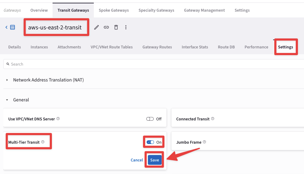
Fig. 421 Multi-Tier Transit#
Let’s verify once again the routing table of the Spoke Gateway in azure-west-us-spoke2.
Go to CoPilot > Cloud Fabric > Gateways > Spoke Gateways > select the relevant gateway azure-west-us-spoke2
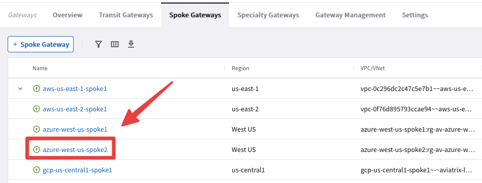
Fig. 422 azure-west-us-spoke2#
This time if you click on the "Gateway Routes" tab, you will be able to see the destination route, 10.0.12.0/24, in aws-us-east1-spoke1 VPC.
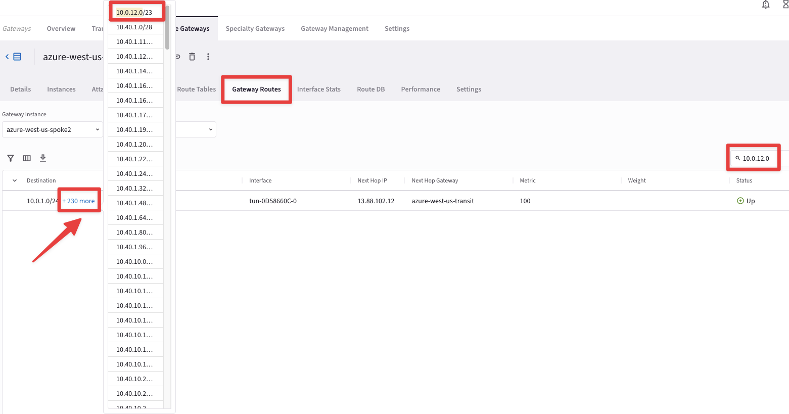
Fig. 423 10.0.12.0/24#
SSH to the Public IP of the instance azure-west-us-spoke2-test1.
Ping the following instance:
aws-us-east-1-spoke1-test2 in AWS (refer to your personal POD portal for the private IP).

Fig. 424 Ping#
Although this time there is a valid route to the destination, thanks to the MTT feature, the pings still fails.
Warning
The reason is that the ec2-instance aws-us-east-1-spoke1-test2 is not allocated to any Smart Groups yet!
6.2 Smart Group “east1”#
Let’s create another Smart Group for the test instance aws-us-east-1-spoke1-test2 in US-EAST-1 region in AWS.
Go to Copilot > Groups > SmartGroups and click on "+ SmartGroup" button.
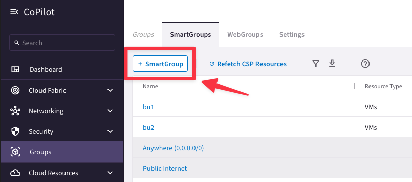
Fig. 425 New Smart Group#
Ensure these parameters are entered in the pop-up window "Create SmartGroup":
Name: east1
CSP Tag Key: Name
CSP Tag Value: aws-us-east-1-spoke1-test2
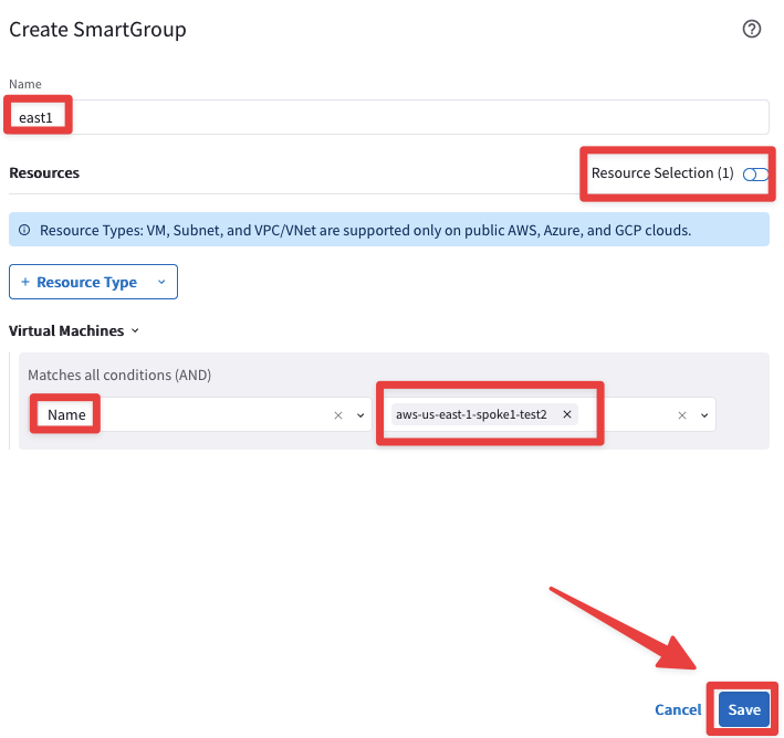
Fig. 426 Resource Selection#
The CoPilot shows that there is just one single instance that matches the condition:
aws-us-east-1-spoke1-test2 in AWS
Do not forget to click on Save.
6.3 Create an inter-rule that allows ICMP from bu2 towards east1#
Go to CoPilot > Security > Distributed Cloud Firewall > Rules (default tab) and create another rule clicking on the "+ Rule" button.
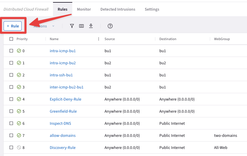
Fig. 427 New Rule#
Ensure these parameters are entered in the pop-up window "Create Rule":
Name: inter-icmp-bu2-east1
Source Smartgroups: bu2
Destination Smartgroups: east1
Protocol: ICMP
Logging: On
Action: Permit
Then click on Save In Drafts.
Caution
Please note the direction of this new inter-rule:
FROM bu2 TO east1
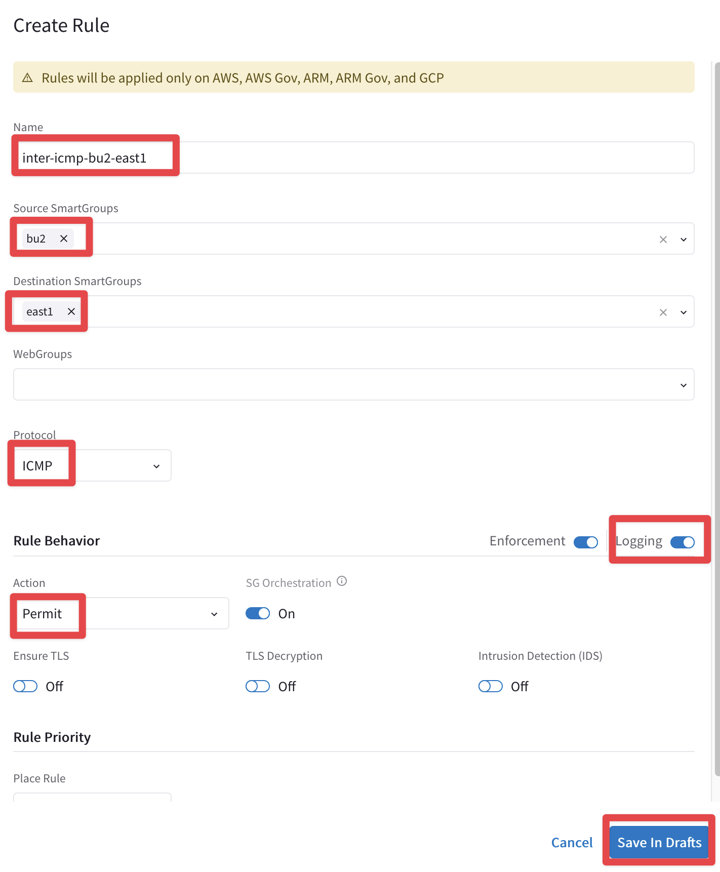
Fig. 428 The Last Rule…#
Now you can carry on with the last commit!
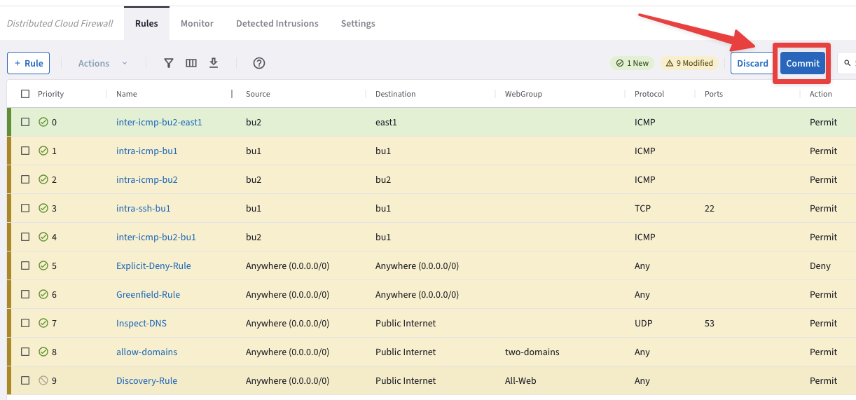
Fig. 429 Commit#
6.4 Verify connectivity between bu2 and east1#
SSH to the Public IP of the instance azure-west-us-spoke2-test1 and ping the private IP of the ec2-instance aws-us-east-1-spoke1-test2
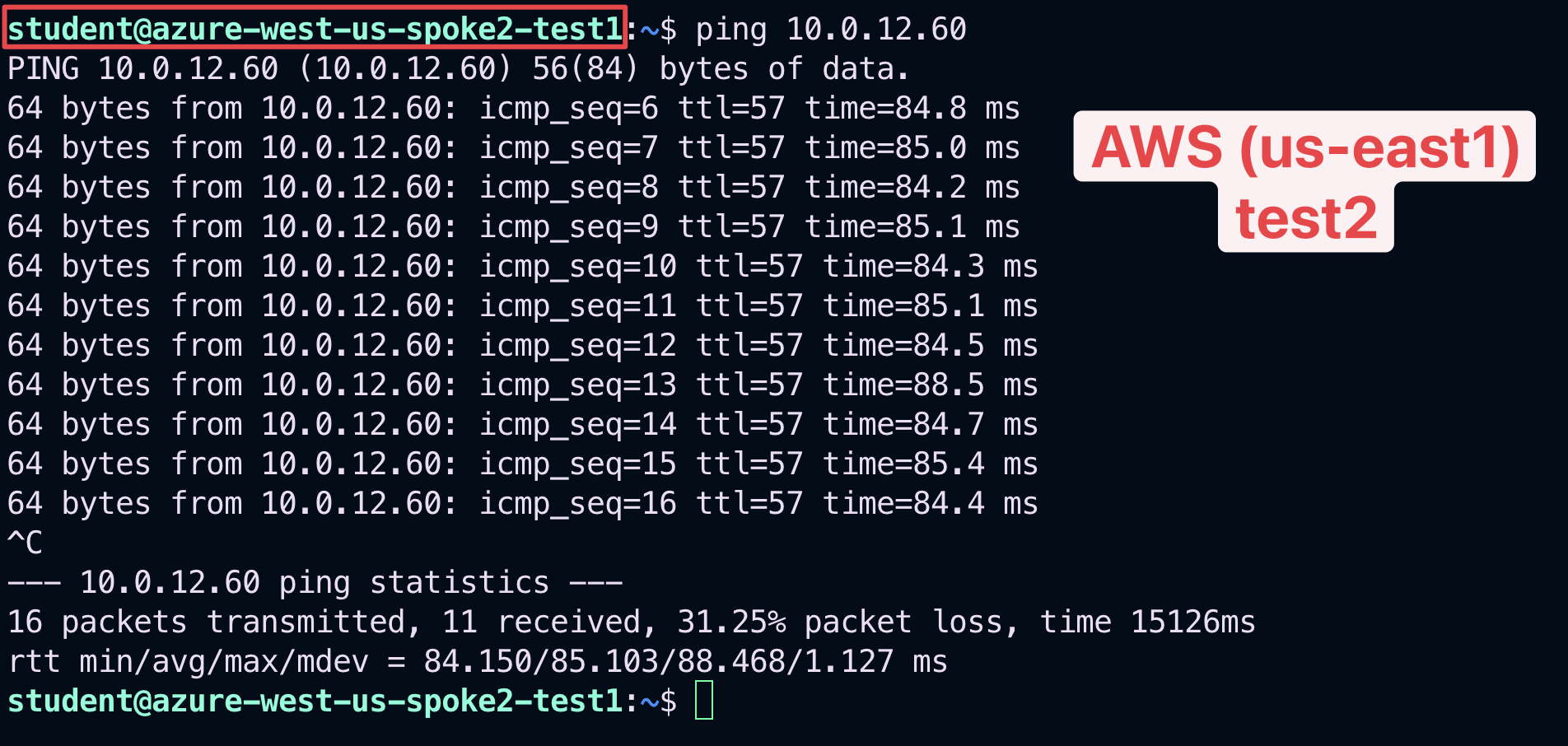
Fig. 430 Ping#
This time the ping will be successful!
Check the logs once again.
Go to CoPilot > Security > Distributed Cloud Firewall > Monitor
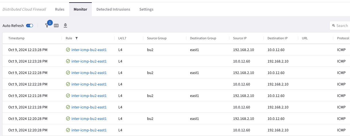
Fig. 432 inter-icmp-bu2-east1 Logs#
After the creation of both the previous inter-rule and the additional Smart Group, this is how the topology with all the permitted protocols should look like.
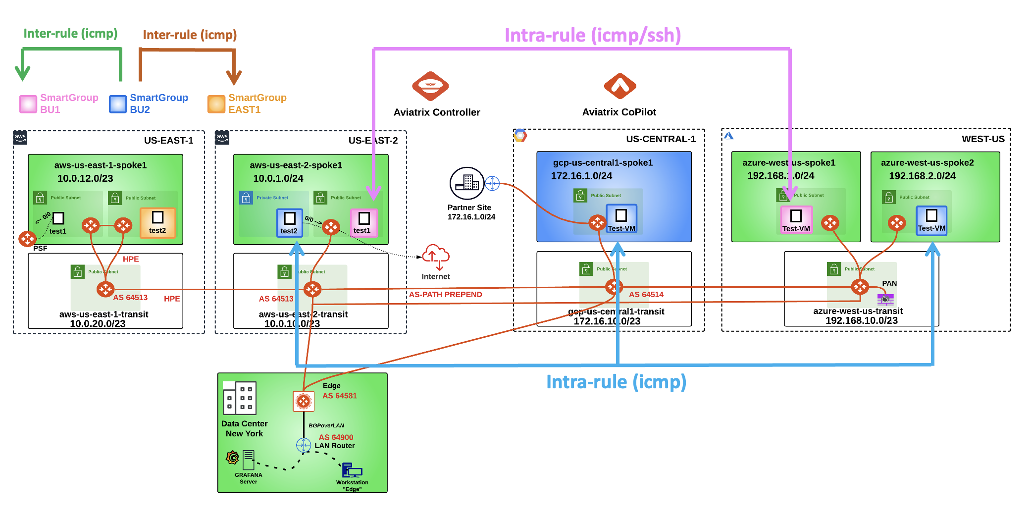
Fig. 433 Final Topology#
7. Spoke to Spoke Attachment#
Now that you have enabled the Distributed Cloud Firewall, the owner of the azure-west-us-spoke2-test1 VM would like to communicate directly with the nearby azure-west-us-spoke1-test1 VM, avoding that the traffic generated from the VNet is sent to the NGFW, first.
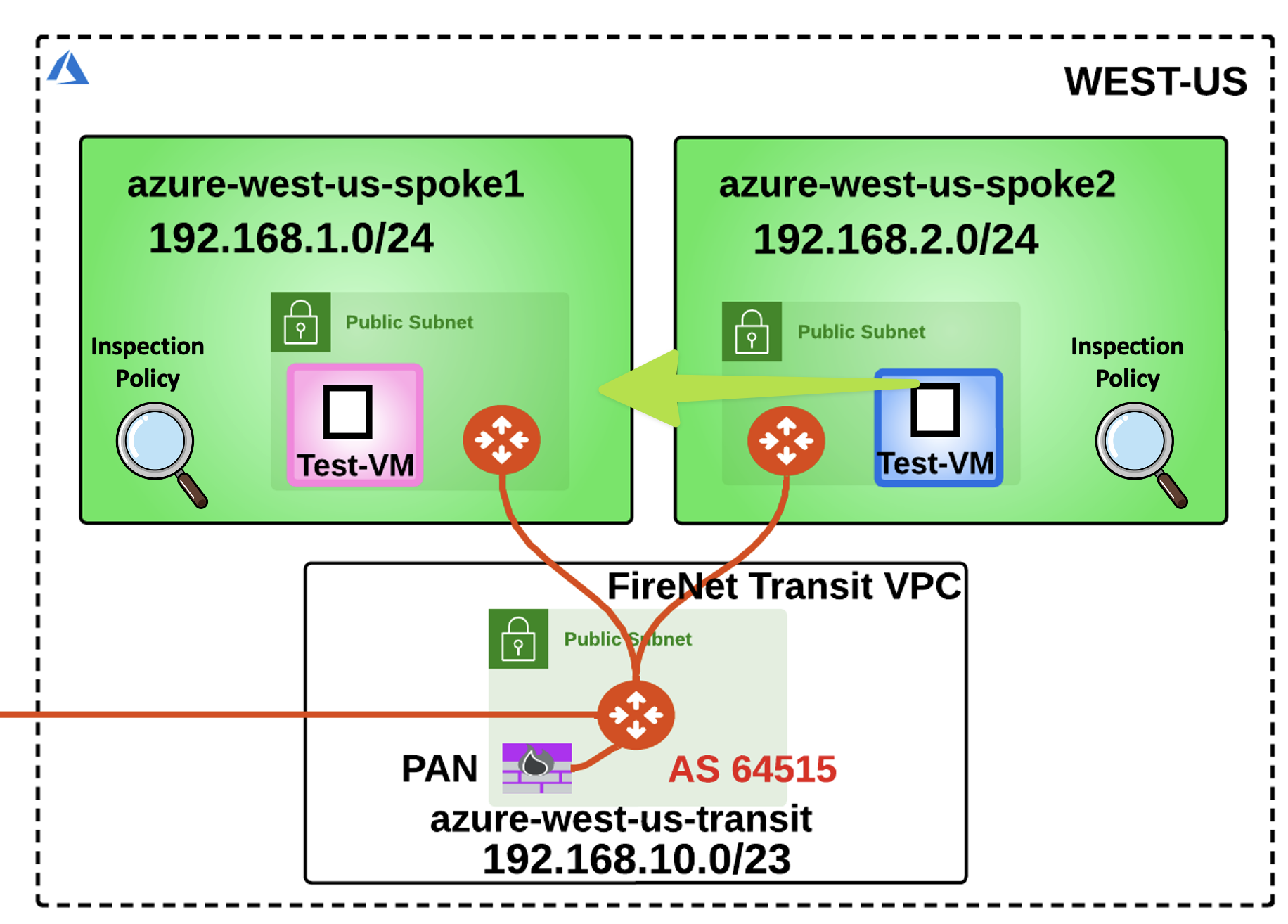
Fig. 434 No More NGFW#
7.1 Creating a Spoke to Spoke Attachment#
Go to Copilot > Cloud Fabric > Gateways > Spoke Gateways, locate the azure-west-us-spoke2 GW and click on the Manage Gateway Attachments icon on the right-hand side.

Fig. 435 Manage Gateway Attachments#
Select the Spoke Gateway tab, click on the "+ Attachment" button and then choose the azure-west-us-spoke1 GW from the drop-down window.
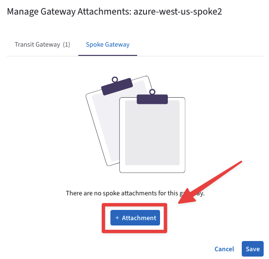
Fig. 436 azure-west-us-spoke2#
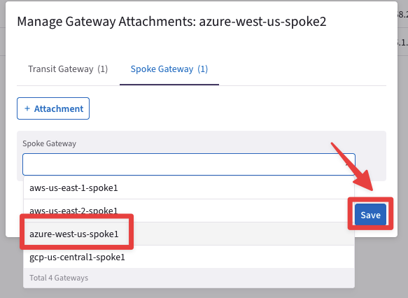
Fig. 437 Save#
Do not forget to click on Save.
Now go to CoPilot > Cloud Fabric > Topology and check the new attachment between the two Spoke Gateways in Azure.
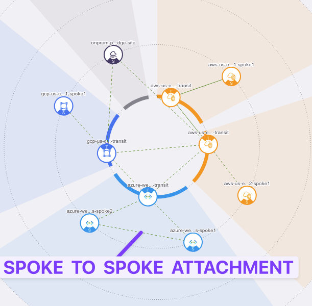
Fig. 438 Spoke to Spoke Attachment#
Caution
It will take approximately 2 minutes to reflect into the Topology.
Let’s check the Routing Table of the Spoke2 in Azure.
Go to CoPilot > Cloud Fabric > Gateways, select the azure-west-us-spoke2, then select the Gateways Routes tab and search for the subnet 192.168.1.0 on the right-hand side.
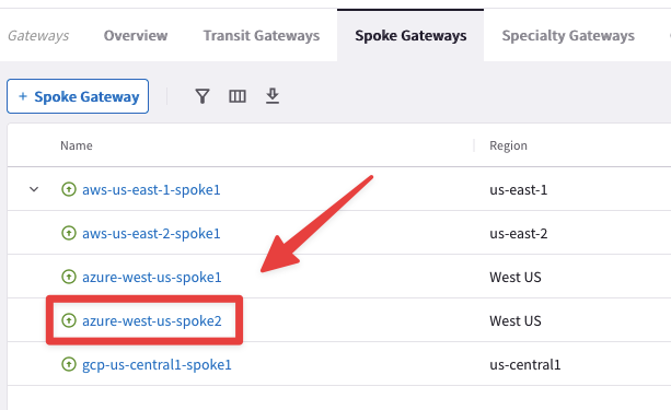
Fig. 439 azure-west-us-spoke2#
You will notice that the destination is now reachable with a lower metric (50)!

Fig. 440 Metric 50#
The traffic generated from the azure-west-us-spoke2-test1 VM will now prefer going through the Spoke-to-Spoke Attachment, for the communication with the Spoke1 VNet.
Important
The Aviatrix Cloud Fabric is very flexible and does not lock you in with solely a Hub and Spoke Topology!
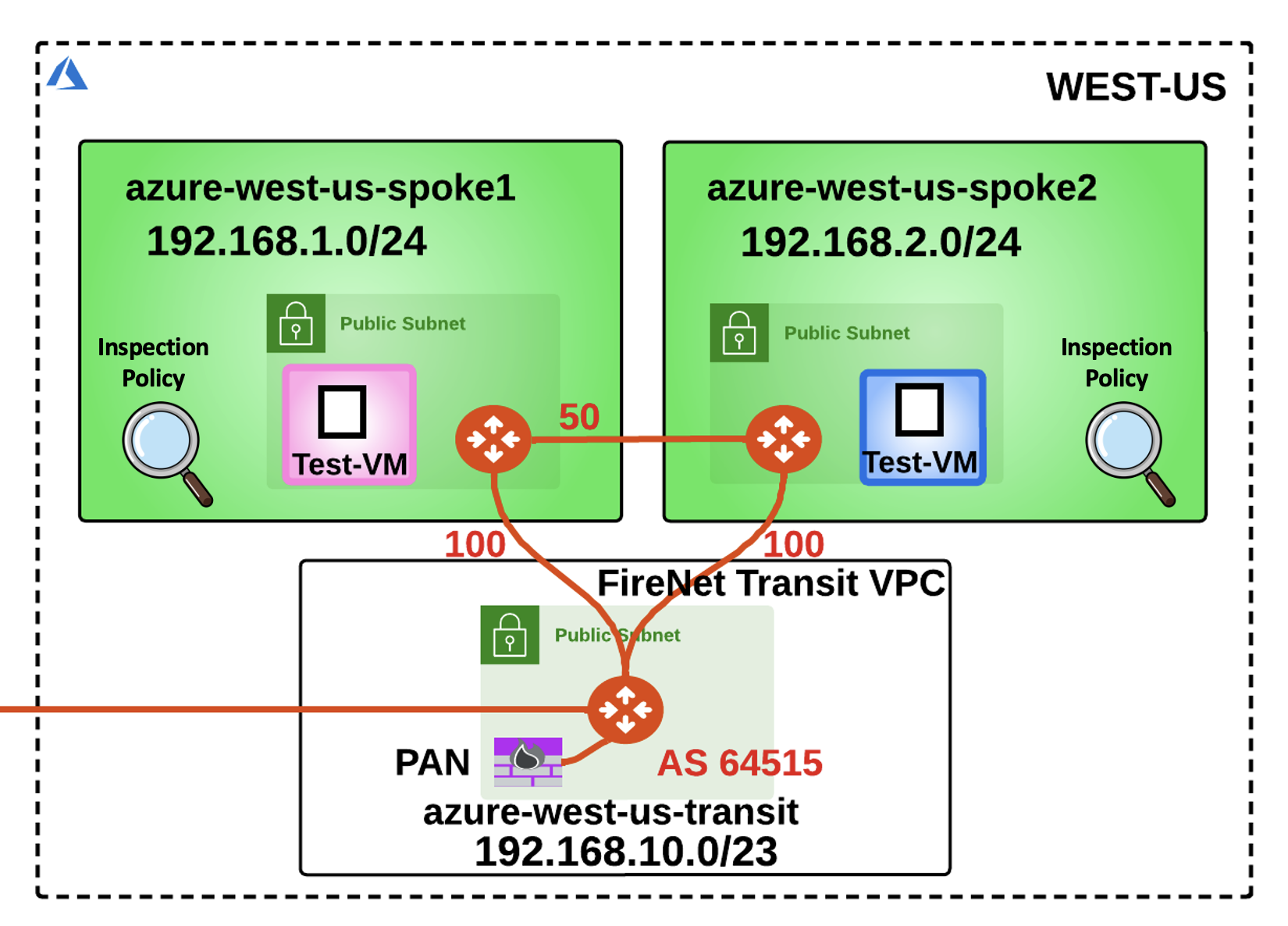
Fig. 441 Spoke to Spoke#
After this lab, this is how the overall topology would look like:
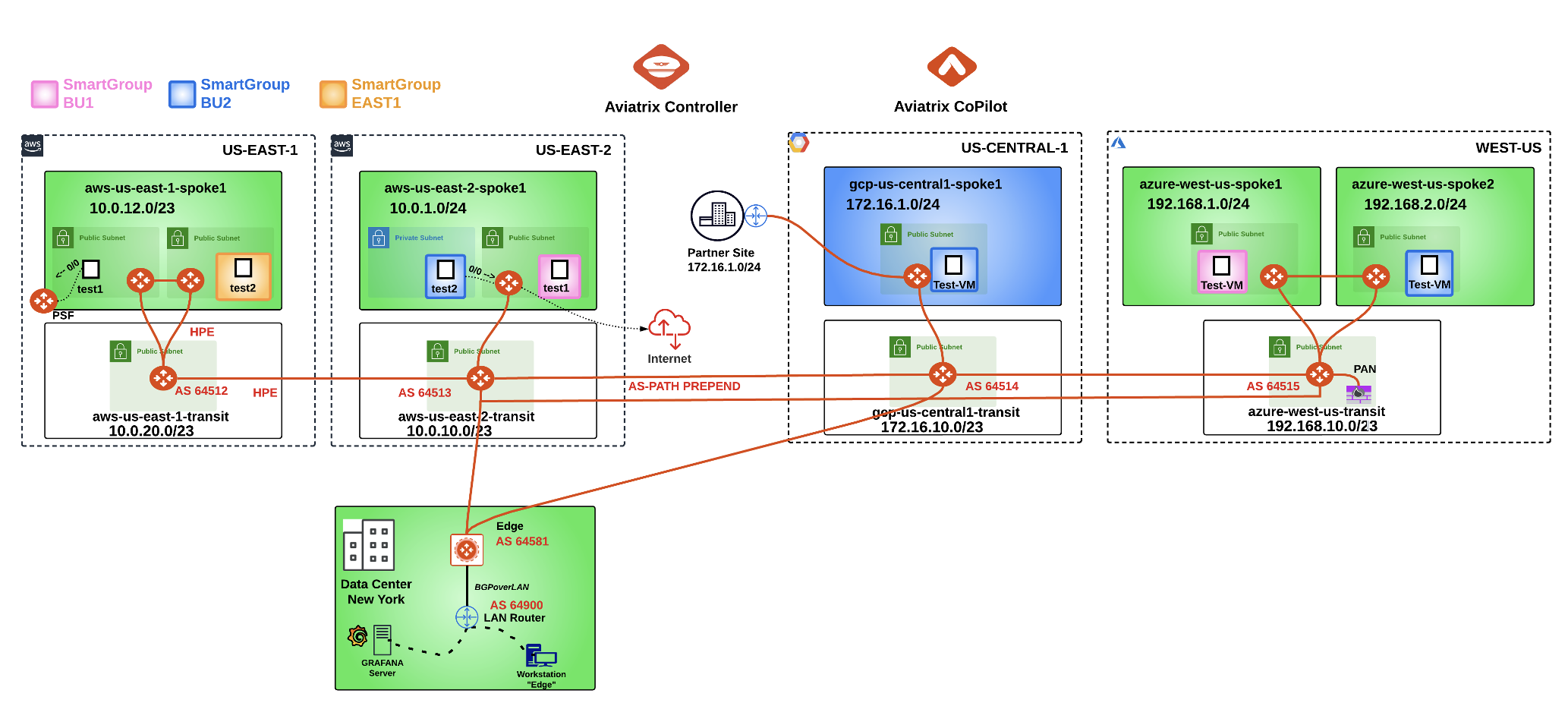
Fig. 442 Full-Blown Aviatrix Solution#

