Lab 4 - HPE WITH ACTIVE MESH#
1. Objective#
In this lab, we will demonstrate Active/Active communication between the resources utilizing high performance encryption (aka Insane Mode - large number of A/A tunnels) between Aviatrix Gateways (Spoke-to-Transit & Transit-to-Transit).
2. High Performance Encryption and ActiveMesh#
Encryption in Cloud could be a compliance, security or business requirement. Hybrid cloud connectivity and in the cloud communication is untrusted. Aviatrix HPE provides high performance end-end encryption from on-prem (private/public connections) to the cloud walled-gardens, between the regions and clouds. It can also help overcome native constructs routing scalability challenges.
Aviatrix ActiveMesh technology provides network resiliency, better convergence and high performance. Both Aviatrix gateways in transit and spoke VPC/VNet/VCNs forward traffic simultaneously. It helps enterprises in traffic engineering and provides deterministic next hop based on path-selection algorithm.
3. Topology#
In this lab we will configure the pending attachment between the Spoke Gateways in aws-us-east-1-spoke1 and the Transit Gateway in aws-us-east-1-transit, and the peering between the Transit Gateway aws-us-east-1-transit and the Transit Gateway in aws-us-east-2-transit. The Gateway in AWS region us-east-1 is pre-configured with HPE (High Performance Encryption, also known as Insane Mode) and AWS us-east-2 region was configured in Lab 3.
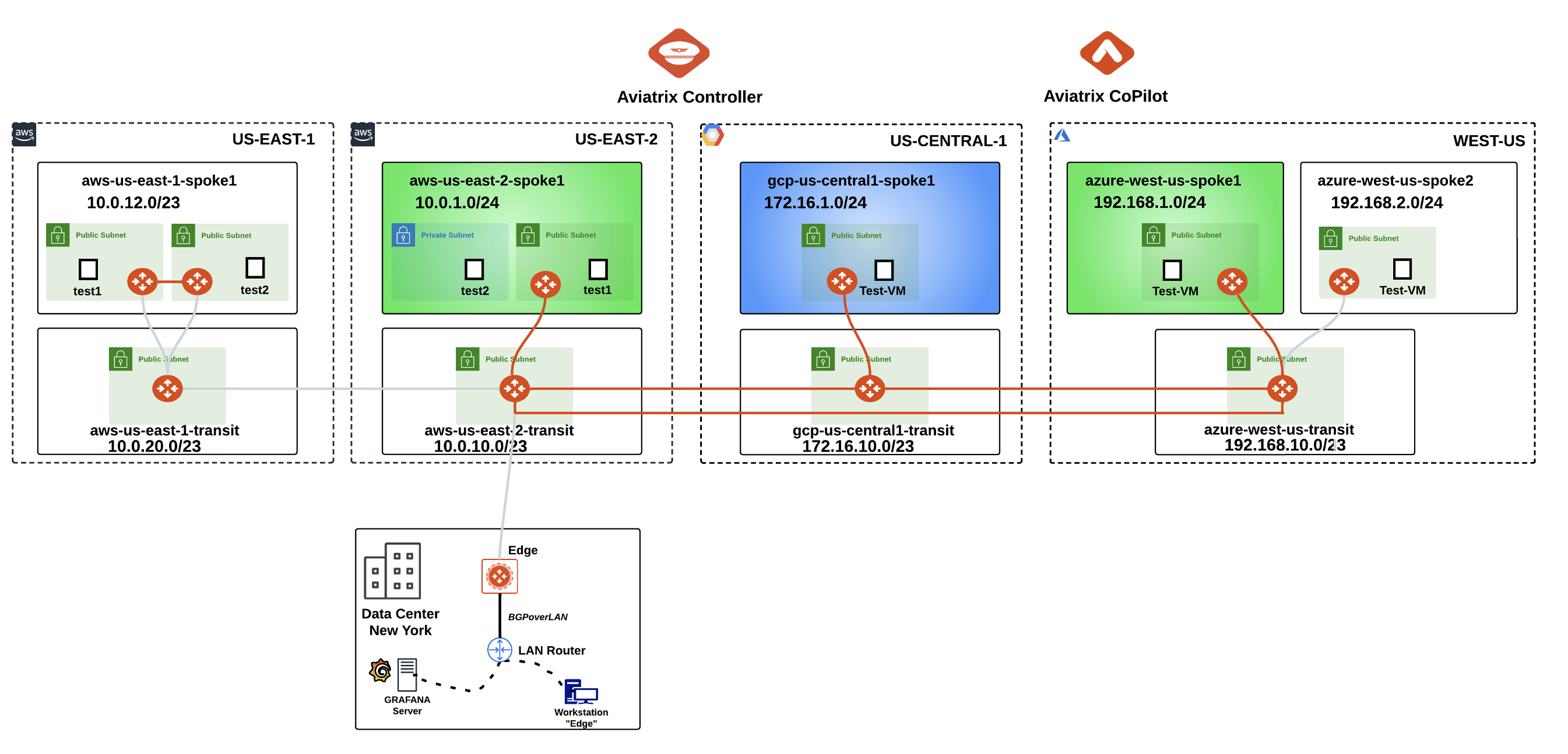
Fig. 107 Lab 5 Topology#
Note
Please keep in mind that the Spoke Gateway in azure-west-us-spoke2 VPC will still remain unattached in this lab!
4. High Performance Encryption Configuration#
4.1. CoPilot View before starting#
Go to CoPilot > Cloud Fabric > Topology > Overview
Important
Verify that AWS US-EAST-1 region has a Transit gateway and a Spoke gateway that are not connected yet.
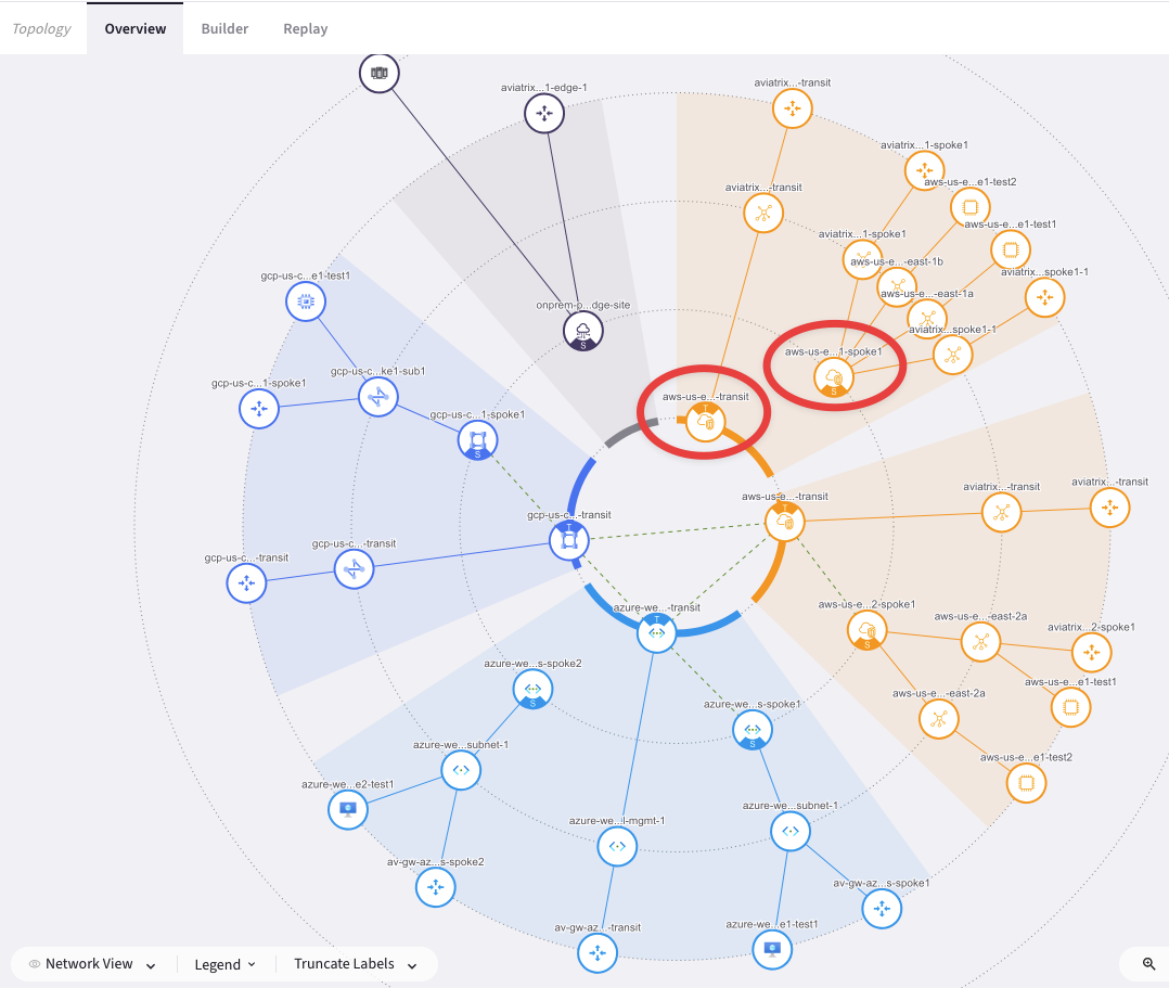
Fig. 108 CoPilot view#
4.2. Transit-Spoke Attachment#
Go to CoPilot > Cloud Fabric > Gateways > Spoke Gateways and edit the Spoke Gateway aws-us-east-1-spoke1 clicking on the pencil icon:

Fig. 109 Edit Spoke US-East-1#
Select the Transit Gateway aws-us-east1-transit from the drop-down window "Attach To Transit Gateway", and then click on Save.
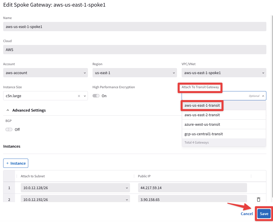
Fig. 110 Attachment#
4.3. CoPilot View after Transit-Spoke Attachment#
Go to CoPilot > Cloud Fabric > Topology > Overview
Verify that both aws-us-east-1-transit gateway and aws-us-east-1-spoke1 gateway are now connected.
Tip
Wait a handful of minutes and then refresh the web page, in order to see the changes applied on the topology!
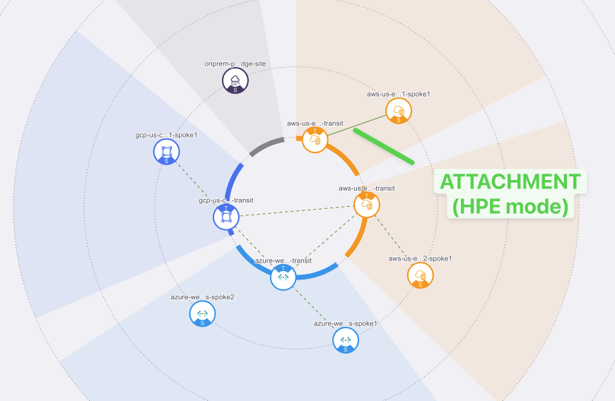
Fig. 111 Attachment on the CoPilot#
Important
Solid line = HPE connection
Dashed line = Non-HPE connection
4.4. Transit Peerings Configuration#
Here you will configure Transit Peering between aws-us-east-1 and aws-us-east-2 regions.
Go back to CoPilot > Cloud Fabric > Gateways > Transit Gateways
aws-us-east-1-transit to aws-us-east-2-transit
Edit the Transit Gateway aws-us-east-1-transit, clicking on the pencil icon:

Fig. 112 Edit Transit in US-EAST-1#
Select the Transit Gateway aws-us-east-2-transit from the drop-down window "Peer To Transit Gateways", and then click on Save.
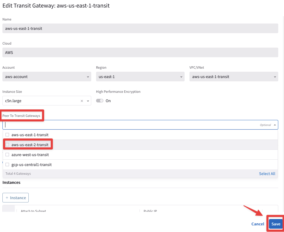
Fig. 113 Peering#
4.4.1. Transit Peerings Verification#
Go to CoPilot > Cloud Fabric > Gateways > Transit Gateways, select the Transit Gateway aws-us-east-1-transit, select the "Gateway Routes" tab and check the route 10.0.1.0/24 for instance.
Note
It may take a minute or two to reflect here.
You will find out that the route 10.0.1.0/24 is reachable through nine connections with the aws-us-east-2-transit.
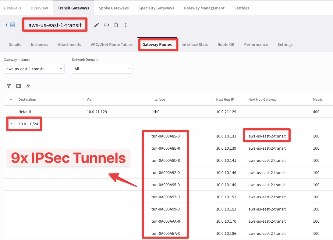
Fig. 114 HPE in action#
Important
The number of additional connections depend on the size of the Aviatrix Gateway.
At this point, this is how the overall topology would look like:
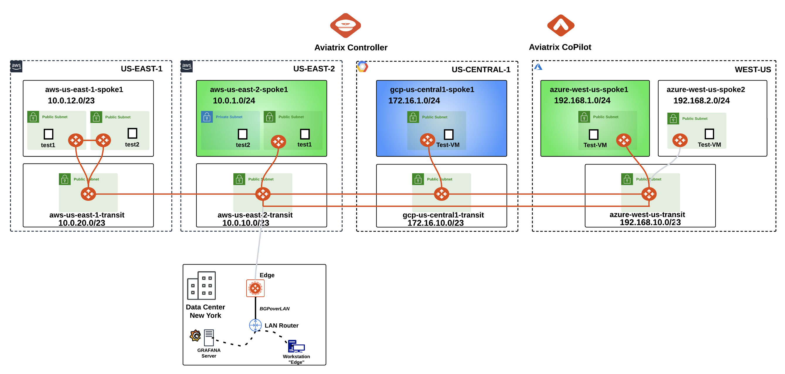
Fig. 115 Logical Topology View#
This is the topology view from CoPilot at this stage:
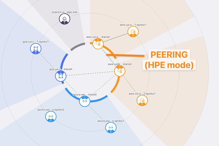
Fig. 116 CoPilot Topology View#
Caution
The actual configuration of High Performance Encryption on both the aws-us-east-1-transit and the aws-us-east-1-spoke1 was done when the gateways were created before this lab.
5. High Performance Encryption Verification#
5.1. CoPilot Verification of the VPC Peerings(Transit-Transit and Spoke-Transit)#
HPE automatically creates an underlying VPC Peering attachment within AWS. Verify it on the CoPilot.
Go to CoPilot > Networking > Connectivity > Native Peering

Fig. 117 Native Peerings#
Click on any VPC peerings to expand its properties on the right side.

Fig. 118 Native Peerings Properties#
5.2. CoPilot Verification of HPE#
Go to CoPilot > Cloud Fabric > Gateways > Transit Gateways, select the Transit Gateway aws-us-east-1-transit, select the "Interfaces" tab and check the huge number of tunnel interfaces that HPE has instantiated.
These tunnels are used with the Spoke Gateway aws-us-east-1-spoke1 and the Transit Gateway aws-us-east-2-transit, because HPE is also enabled on these gateways:
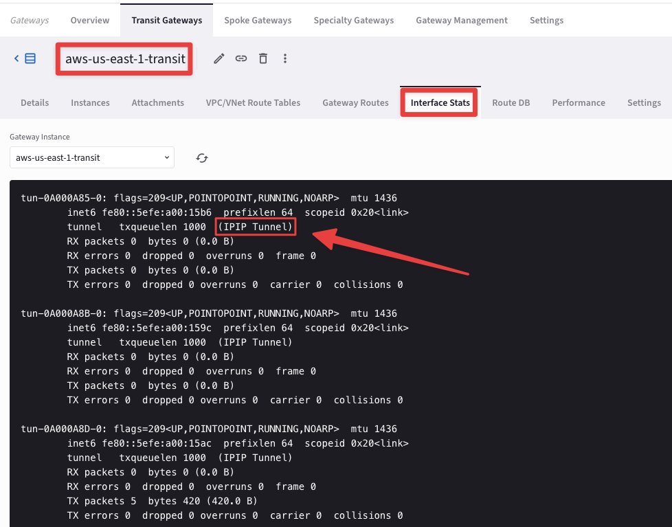
Fig. 119 Interface Stats#
6. ActiveMesh#
6.1. CoPilot Verification of ActiveMesh#
Go to CoPilot > Diagnostics > Cloud Routes > VPC/VNet Routes
Click the filter button, select “Name” and enter aws-us-east-1-spoke1-Public-1-us-east-1a-rtb to filter by just that route table.
Note
The RFC 1918 summary routes points to the Aviatrix Spoke gateway for this routing table programmed by the Aviatrix Controller:

Fig. 120 Filter#
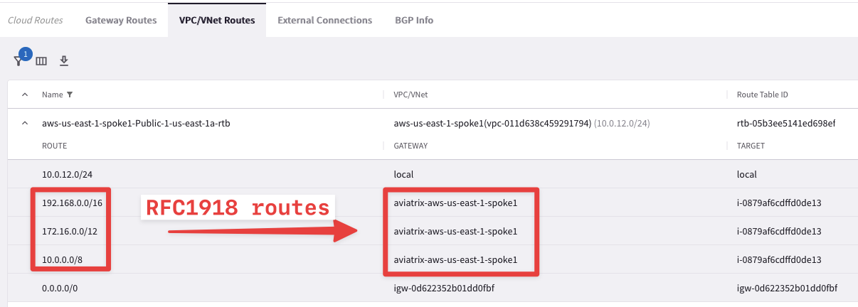
Fig. 121 RFC1918 routes pointing towards the First Spoke GW#
Now remove the previous filter and select aws-us-east-1-spoke1-Public-2-us-east-1b-rtb.
Note
This time the RFC 1918 summary routes points to the Aviatrix Second Spoke gateway for this routing table programmed by once again the Aviatrix Controller:

Fig. 122 Filter#
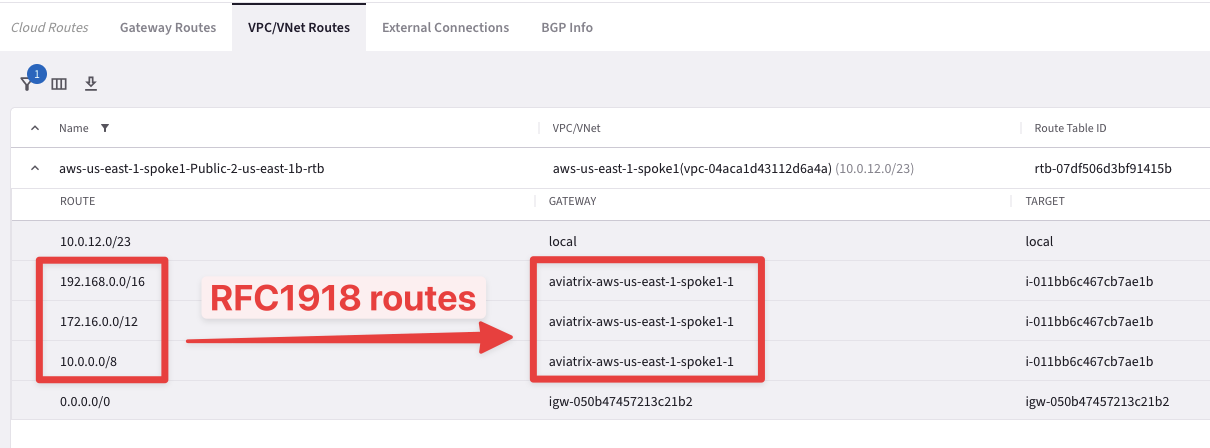
Fig. 123 RFC1918 routes pointing towards the Second Spoke GW#
As you can see, Active/Active is achieved within a VPC as well. Each gateway is active on the Availability Zone where it resides.
6.2. Connectivity test of ActiveMesh (Pt.1)#
Test that the EC2 instances in two subnets are pointing to two different routing tables. If one gateway goes down, the controller will switch the ENI of the available gateway in the routing table.
SSH into both EC2 test instances in aws-us-east-1-spoke1 VPC (refer to your Pod assignment).
These test instances are in separate AZs and their default gateways are two different Aviatrix Spoke gateways in their respective AZs.
Ping the EC2 test instance (10.0.1.100) in aws-us-east-2-spoke1 VPC.
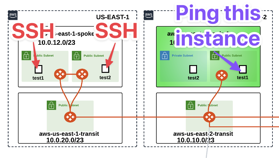
Fig. 125 From US-EAST-1 to US-EAST-2#
It will fail. WHY? Because we didn’t enable segmentation on aws-us-east-1-transit and associate aws-us-east-1-spoke1 with the transit gateway in the appropriate network domain.
6.2.1 Enable Segmentation#
Go to CoPilot > Networking > Network Segmentation > Network Domains > Transit Gateways
Enable Segmentation on aws-us-east-1-transit:
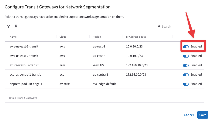
Fig. 126 Enable Segmentation#
6.2.2. Associate Aviatrix Spoke to the Network Domain#
Go to CoPilot > Networking > Network Segmentation > Network Domains
Associate aws-us-east-1-spoke1 with its transit in the Green network domain:
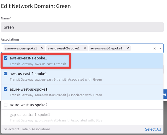
Fig. 127 Association#
At this point, this is how the overall topology would look like:
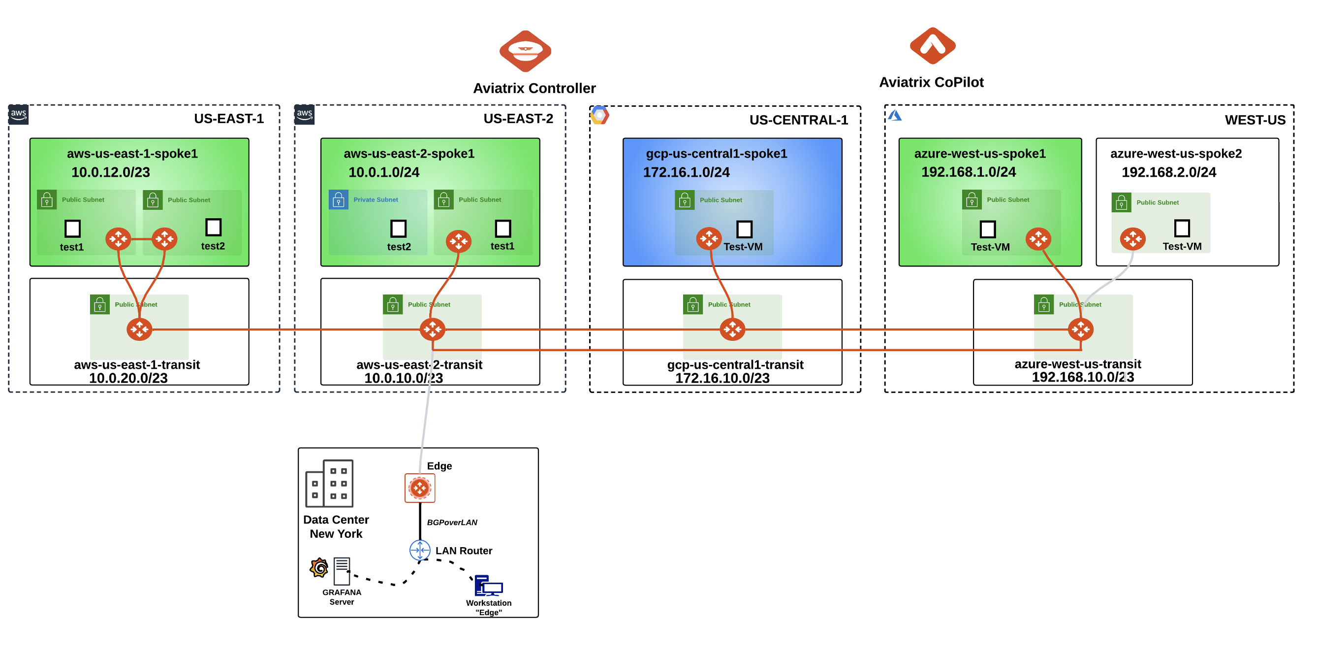
Fig. 128 New Logical Topology View#
6.3. Connectivity test of ActiveMesh (Pt.2)#
Now from to the aws-us-east-1-spoke1-test1 in AWS US-East1, launch the ping command towards the aws-us-east-2-spoke1-test1 in AWS US-East2.
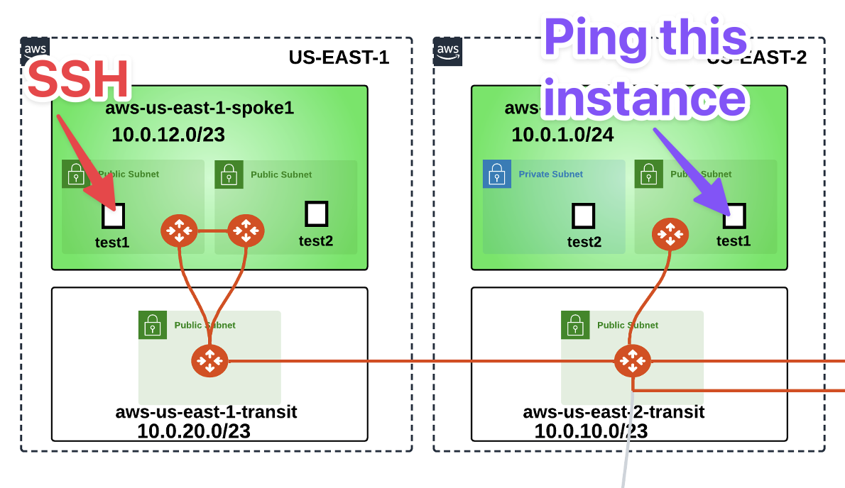
Fig. 129 Instances are now in the same Segment!#

Fig. 130 ping from aws-us-east-1-spoke1-test1#
Repeat the ping from the aws-us-east-1-spoke1-test2 in AWS US-East1 towards aws-us-east-2-spoke1-test1 in AWS US-East2.
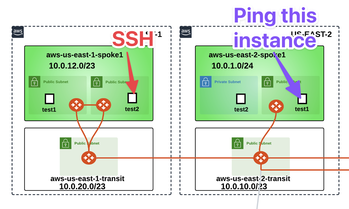
Fig. 131 Second ping#

Fig. 132 ping from aws-us-east-1-spoke1-test2#
Important
Please keep both the ping sessions running recursively on your SSH client! Don’t interrupt the ping.
To demonstrate ActiveMesh capability, you will shut down temporarily one of the spoke gateways and notice traffic converging to the other gateway.
Login to AWS console. Refer to your pod info for login information (this screenshot is for Pod 149).
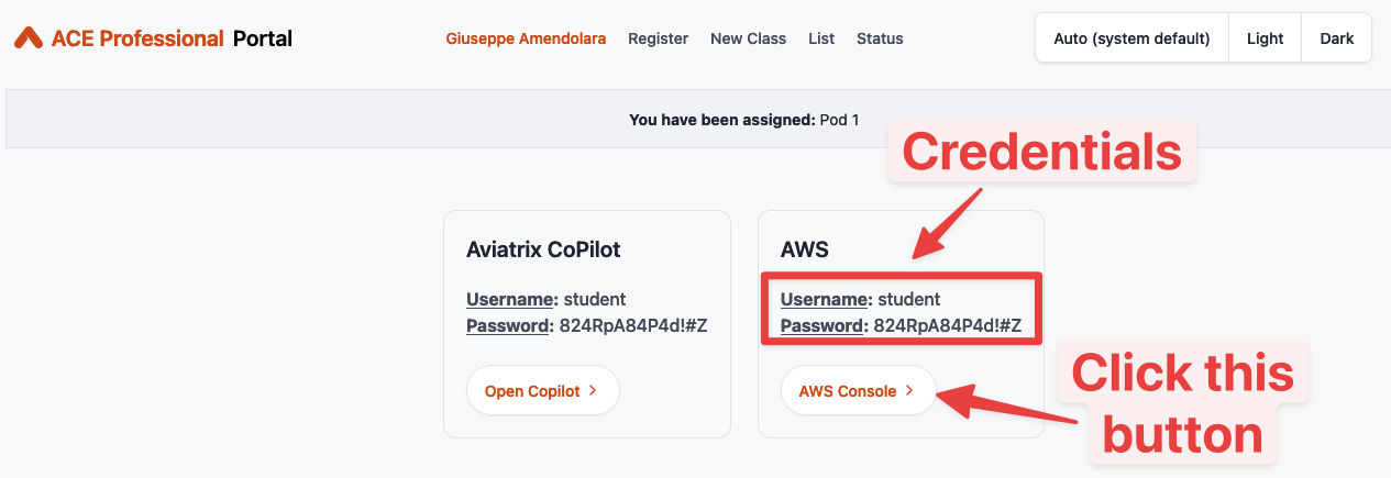
Fig. 133 AWS URL and credentials#
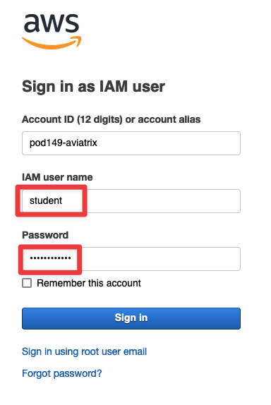
Fig. 134 AWS console#
Change the region to N. Virginia and invoke EC2 service.

Fig. 135 Change the region#
Click on Instances (running):
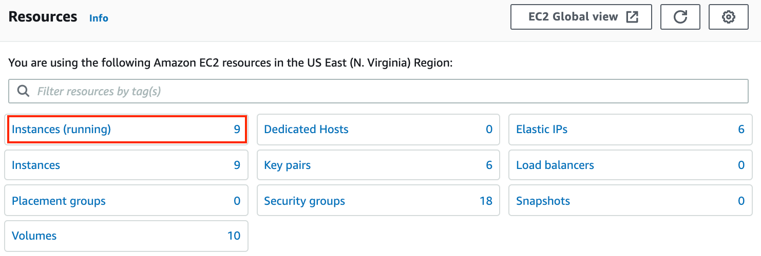
Fig. 136 Instances running#
Search for aviatrix-aws-us-east-1-spoke1 and then select Instance state > Stop instance

Fig. 137 Stop the Instance#
Confirm by clicking on Stop one more time.
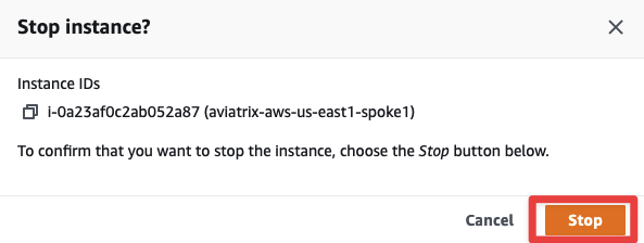
Fig. 138 Confirm the stop#
You will notice ping drops solely from aws-us-east-1-spoke1-test1. The traffic will reconverge to the spoke gateway in the other AZ, in about 1 minute and 30 seconds to 2 minutes.
This shows how the Aviatrix Controller intelligently auto-heals the VPC routing.
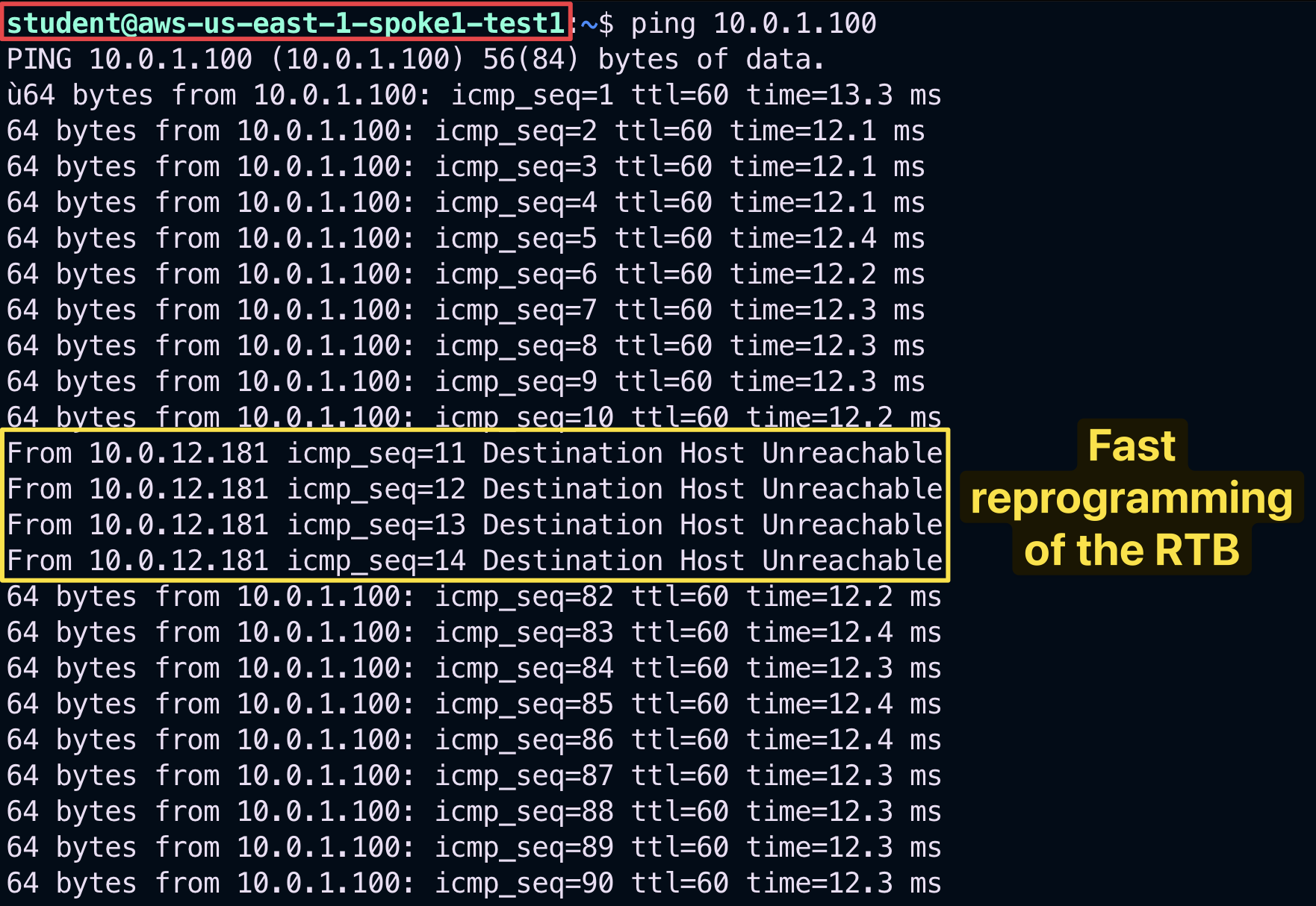
Fig. 139 Temporary disruption with FAST keepalive!#
Bonus Step: Restart the Gateway from the AWS console and reverify the traffic flow. This time you will not notice any disruption: the traffic flow fill switch back to the aviatrix-aws-us-east-1-spoke1 GW.

Fig. 140 Restart#
After this lab, this is how the overall topology would look like:
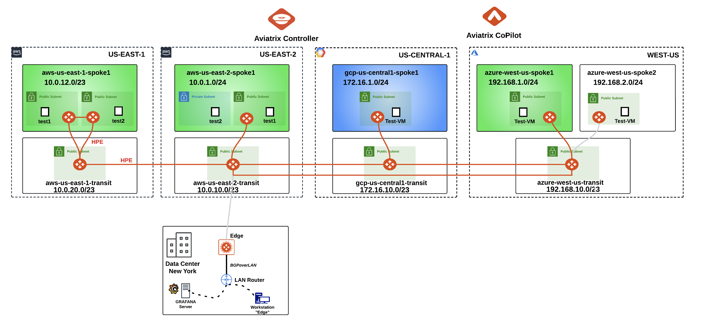
Fig. 141 Final Topology for Lab 5#
7. FlightPath#
Go to CoPilot > Diagnostics > AppIQ > FlightPath
Use the following inputs:
Source: aws-us-east-1-spoke1-test1
Destination: aws-us-east-2-spoke1-test1
Protocol: TCP
Port: 443
Interface: Private

Fig. 142 FlightPath config#
This will provide an AppIQ report of how aws-us-east-1-spoke1-test1 is connected with aws-us-east-2-spoke1-test1 and display the path along with end-to-end latency.
Note
You might see some links still depicted in red, after having restarted the Spoke Gateway. Be patient and relaunch the report and you will get the same outcome as depicted below.
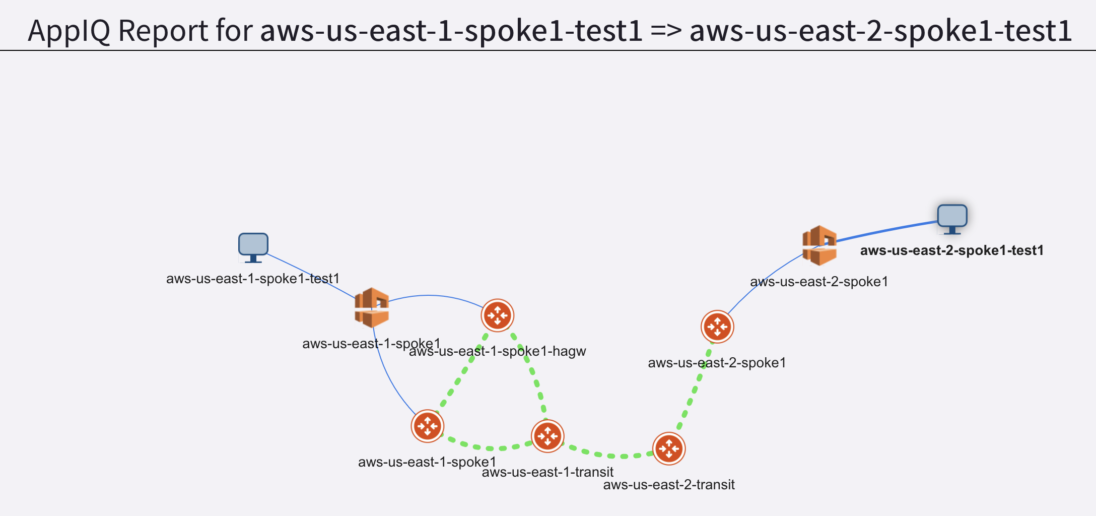
Fig. 143 FlightPath Report#
Scroll down to get more details about:
The latency between each pair of gateways
Performance monitoring metrics of all gateways in the path
FlowIQ between the two instances
Security group checks
NACL checks
Routing tables
You can also download the entire report in pdf format by clicking the PDF icon at the top right corner:

Fig. 144 FlightPath Report PDF#
Bonus questions#
Gateway Keepalive Templates#
Experiment with GATEWAY TO CONTROLLER COMMUNICATION and retest convergence times when bringing down a spoke gateway.
Tip
You can modify the Gateway to Controller Communication timer directly from the CoPilot. Go to CoPilot > Cloud Fabric > Gateways > Settings > Gateway to Controller Communication and change the Keep Alive Speed from medium (default) to fast. Then repeat the experiment carried out earlier.

Fig. 145 Keep Alive Speed#
Transitive Routing#
Warning
The test instances in aws-us-east-1-spoke1 are not able to communicate with the test instances in GCP or in Azure.
You can verify this with the Gateway routing table on the CoPilot > Diagnostics > Cloud Routes > Gateway Routes > aws-us-east-1-transit. You will not see the GCP Spoke routes of 172.16.1.0/24., for instance.
Why is that? What would be needed to make those routes visible?

